A830: TX Audio
Description
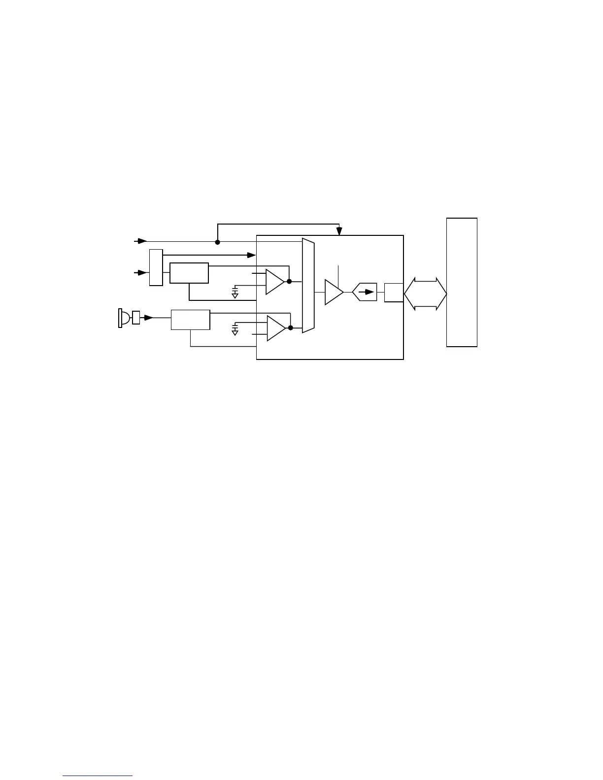
The Internal Microphone is a single ended part. Following the Internal microphone path, the microphone is biased by R4103 to provide a MIC_BIAS of 2.0V from pin
MIC_BIAS1 of PCAP. C4198 is connected to MIC_BIAS1 and MB_CAP1 pin on PCAP to bypass the gain from the VAG to MIC_BIAS1 which keeps the noise balanced. From
there, the signal is routed through C4100 to AUX_OUT pin on PCAP, bypassing the input to the A5 amplifier.
The headset microphone path (HS_MIC) is biased through R4396 and R4392, which is connected to pin MIC_BIAS2 on PCAP and bypassed with C4199 connected to pin
MB_CAP2. From here the signal is routed through C4395 and R4388 to MIC_IN- pin on PCAP, which is the input to the A3 Amplifier. The Microphone path is tapped off after
R4388 before the MIC_IN- input to R4389 connected to the MIC_OUT pin on PCAP, which is the output of the A3 Amplifier. The HS_MAKE_DET line monitors the presence
of a headset by detecting the voltage at A1_INT of PCAP, which passes through R4398. A switching mechanism integrated in the headset jack will open or close the
HS_MAKE_DET path to ground, depending on whether the headset is attached or not.
The External Microphone input (AUDIO_IN) is connected to the accessory connector for the mobile phone. The path is routed through L4400, C4401 and R4401 to the
EXT_MIC pin on PCAP. This signal feeds directly to the input multiplexer without an intervening gain stage. In addition to audio signals, AUDIO_IN supports detection of
accessory devices. The accessory attached to the CE bus shall have an output impedance that will load LOGIC_SENSE to a predetermined level. The POG will read the input
level of LOGIC_SENSE and configure the audio accordingly.
The proper Microphone path is selected by the AUD MUX controller and path gain is programmable at the PGA. The A/D converter willl convert incoming analog signals into
13-bit, 2's compliment, linear PCM words. The digital audio signals are then transferred to the POG DSP through a four wire serial interface (ASAP).
Motorola Confidential Proprietary
4-38
MIC GAIN
PCAP
LOGIC_SENSE
MIC_BIAS1
AUX_OUT
AUX_MIC-
Audio Filter
Circuit
MIC
ADC
POG
PGA
AUDIO_IN
MIC_BIAS2
MIC_OUT
Audio Filter
Circuit
AUD MUX
HS_MIC
SSI
ASAP_RX
ASAP_FS
ASAP_CLK
NC
J4300
J4100
A5
A3
HS_MAKE_DETECT
EXT_MIC
NC
VAG
 Loading...