3
Test Procedure
The test procedure for the amplifier-loudspeaker is presented in the
test and troubleshooting procedures pyramid diagram, Figure 2.
Troubleshooting
Procedures
The troubleshooting procedure for the amplifier-loudspeaker are
presented in the test and troubleshooting procedures pyramid
diagram, Figure 2 on page 4.
Roto-Torq Adjustable Torque
Screwdriver
Motorola Kit RSX-4043A
Spanner Nut Bit for Adjustable
Torque Screwdriver
Motorola 66-80371B34
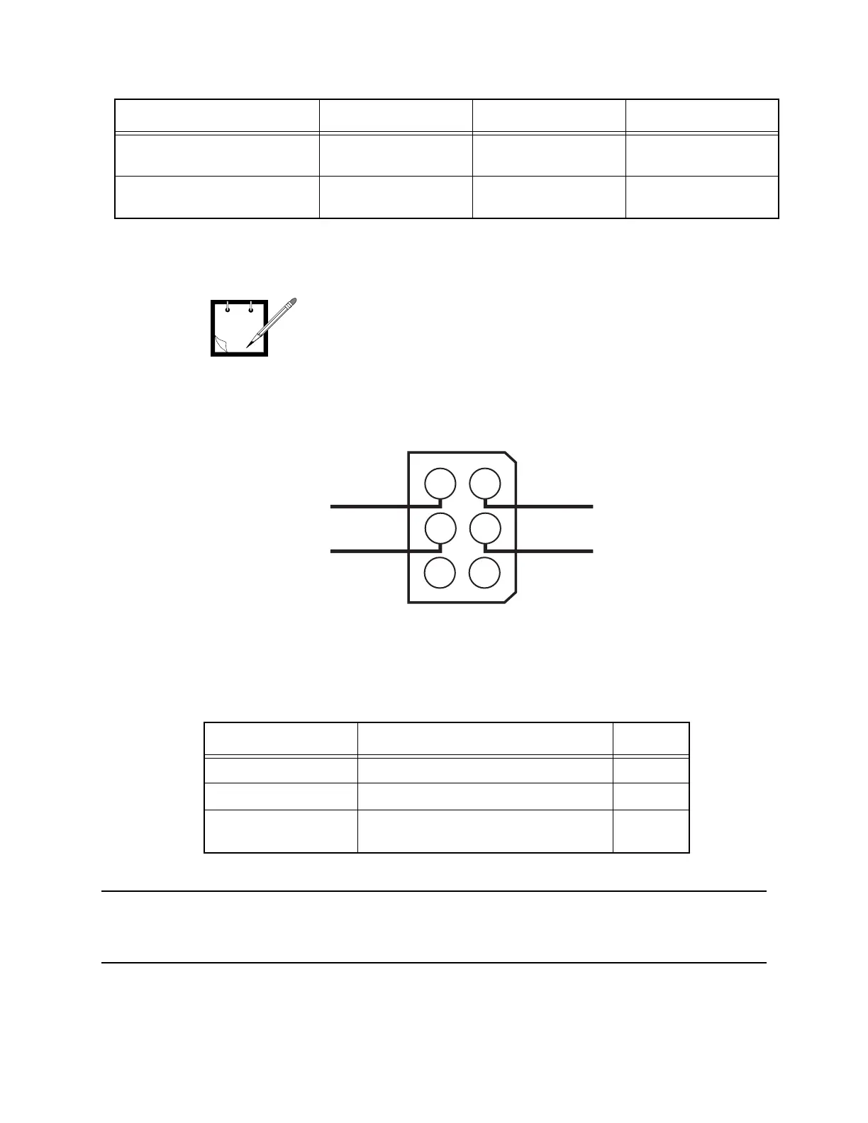
Table 2 Test Connector Components
Motorola Part No. Description Quantity
1584953L01 Molex Connector Body, 6 Pin 1
2984706E06 Molex Connector Pin, Female 4
Not Applicable Hookup Wire, Stranded, Insulated, 18
AWG, 24-Inches Long
4
Table 1 Test Equipment and Special Tools
Description Manufacturer Model No./Part No. Notes
Motorola Test Box RKN4460( ) can be substituted for the
4-Ohm 20-Watt fixed resistor specified in table 1. When pins 2
and 6 of female connector on back of test box are shorted
together and SPKR/LOAD switch on top of test box is set to
LOAD, a suitable 4-Ohm 20-Watt resistance is available
between the two EXTERNAL LOAD jacks on top of test box.
Note
Audio Input
Ground
3
2
1
Analog Ground
B+
6
5
4
Figure 1 Test Connector Schematic/Wiring Diagram
MAEPF-26585-O
 Loading...