6809495A75-O October 14, 2005 27
Level 1 and 2 Service Manual Disassembly
Removing and Replacing the Camera Assembly.
1. Remove the battery cover, battery, SIM, antenna, and transceiver PC board as
described in the procedures..
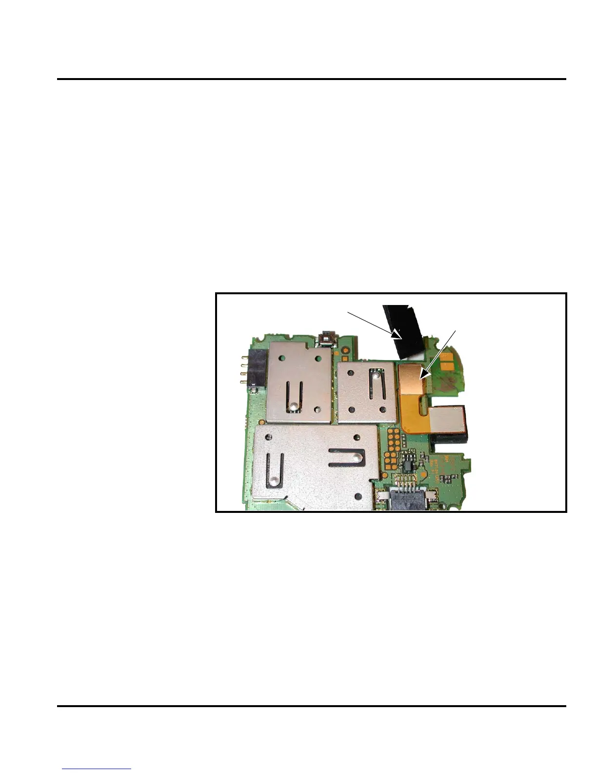
2. Use the disassembly tool to unseat the camera assembly flex connector from
the transceiver PC board assembly (see Figure 16).
3. Lift the camera assembly away from the transceiver PC board.
4. To replace, align the camera grommet to the transceiver PC board
5. Align the camera assembly to the transceiver PC board.
6. Carefully press the camera flex connector into its socket on the transceiver PC
board.
7. Reassemble the transceiver PC board, antenna, SIM, battery and battery cover
as described in the procedures.
G
This product contains static-sensitive devices. Use anti-static handling procedures
to prevent ESD and component damage.
G
The flexible printed cable (FPC) (flex) is easily damaged. Exercise extreme care when
handling.
050784o
Figure 16. Removing the Camera Assembly
Disassembly tool
Camera Flex
Connector
 Loading...