2-29
Hardware Setup
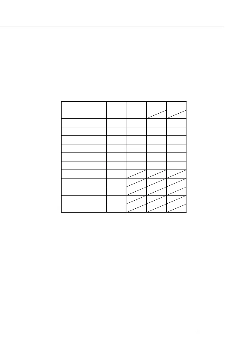
PCI Interrupt Request Routing
The IRQ, abbreviation of interrupt request line and pronounced I-R-Q,
are hardware lines over which devices can send interrupt signals to the
microprocessor. The “AGP/PCI/USB/LAN” IRQ pins are typically connected
to the PCI bus INT A# ~ INT H# pins as follows:
Order 1 Order 2 Order 3 Order 4
AGP INT A# INT B#
PCI Slot 1 INT A# INT B# INT C# INT D#
PCI Slot 2 INT B# INT C# INT D# INT A#
PCI Slot 3 INT C# INT D# INT A# INT B#
PCI Slot 4 INT D# INT A# INT B# INT C#
PCI Slot 5 INT B# INT C# INT D# INT A#
PCI Slot 6 INT A# INT B# INT C# INT D#
USB1.1 Controller 1 INT A#
USB1.1 Controller 2 INT D#
USB1.1 Controller 3 INT C#
USB2.0 Controller INT H#
LAN Controller INT E#
AGP & PCI Slot 1 & PCI Slot 6 & USB1.1 Controller 1 shared INT A#.
PCI Slot 2 & PCI Slot 5 shared INT B#.
PCI Slot 3 & USB1.1 Controller 3 shared INT C#.
PCI Slot 4 & USB1.1 Controller 2 shared INT D#.
 Loading...