2-23
Hardware Setup
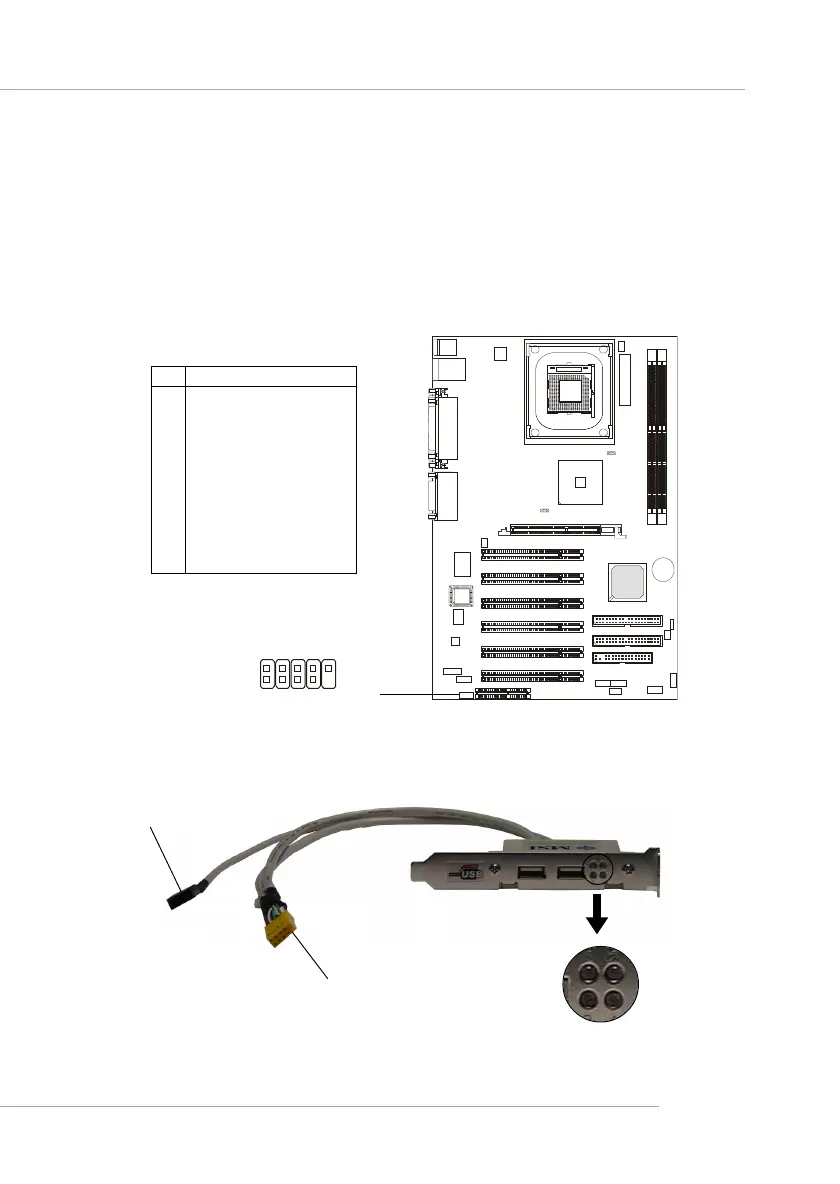
D-Bracket™ 2 Connector: JDB1
The mainboard comes with a JDB1 connector for you to connect to D-
Bracket™ 2. D-Bracket™ 2 is a USB Bracket that supports both USB1.1 &
2.0 spec. It integrates four LEDs and allows users to identify system problem
through 16 various combinations of LED signals. For definitions of 16 signal
combinations, please refer to D-Bracket™ 2 (Optional) in Chapter 1.
Pin Signal
1 DBG1 (high for green color)
2 DBR1 (high for red color)
3 DBG2 (high for green color)
4 DBR2 (high for red color)
5 DBG3 (high for green color)
6 DBR3 (high for red color)
7 DBG4 (high for green color)
8 DBR4 (high for red color)
9 Key
10 NC
JDB1 Pin Definition
D-Bracket™ 2
Connected to JUSB1 (the USB
pinheader in yellow color)
Connected to JDB1
LEDs
JDB1
1 9
2
10
 Loading...