2-20
MS-7082 Micro ATX Mainboard
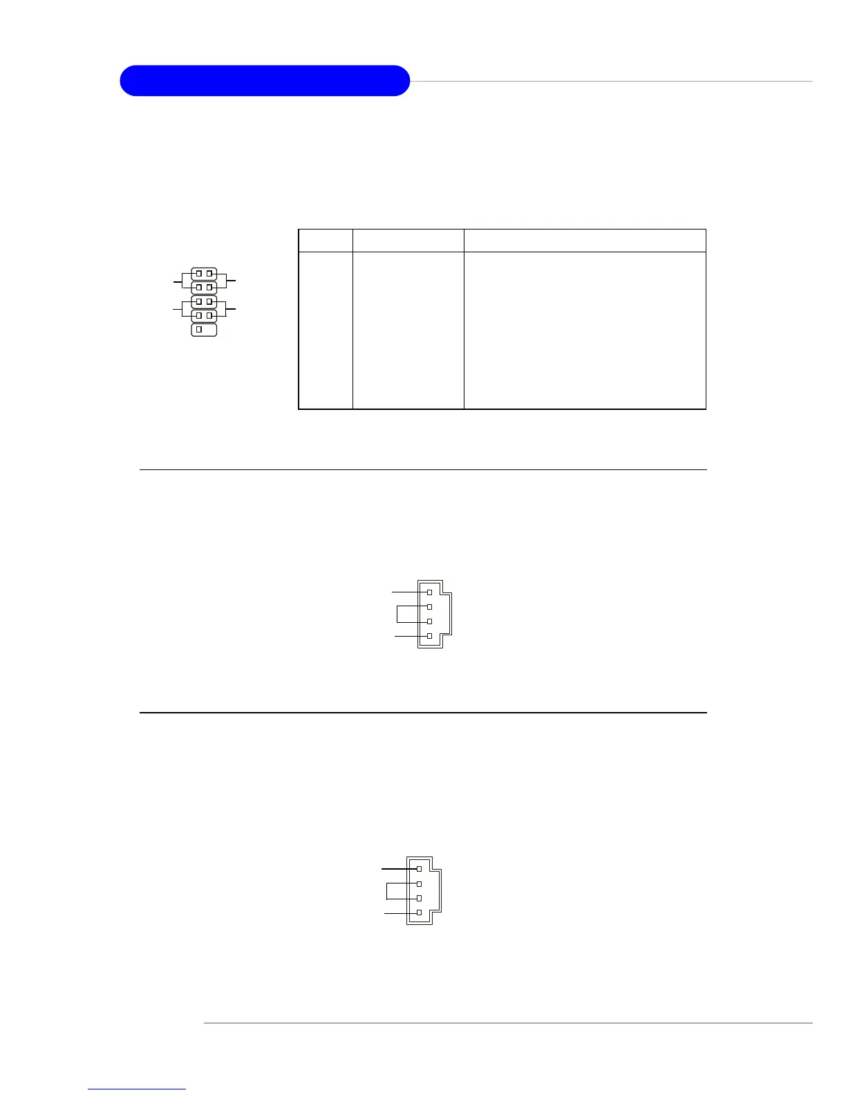
Front Panel Connectors: JFP1
The mainboard provides one front panel connector JFP1 for electrical connection to the
front panel switches and LEDs. It is compliant with Intel
®
Front Panel I/O Connectivity
Design Guide.
1
2
9
10
JFP1
HDD
LED
Reset
Switch
Power
LED
Power
Switch
PIN SIGNAL DESCRIPTION
1 HD_LED_P Hard disk LED pull-up
2 FP PWR/SLP MSG LED pull-up
3 HD_LED_N Hard disk active LED
4 FP PWR/SLP MSG LED pull-up
5 RST_SW_N Reset Switch low reference pull-down to GND
6 PWR_SW_P Power Switch high reference pull-up
7 RST_SW_P Reset Switch high reference pull-up
8 PWR_SW_N Power Switch low reference pull-down to GND
9 RSVD_DNU Reserved. Do not use.
JFP1 Pin Definition
Modem-In Connector: JMD1
The connector is for modem with internal audio connector.
Phone_In
Mono_Out
MDM_IN1
GND
AUX_IN1
GND
R
L
Aux Line-In Connector: AUX_IN1
The connector is for DVD add-on card with Line-in connector.
 Loading...