2-11
Hardware Setup
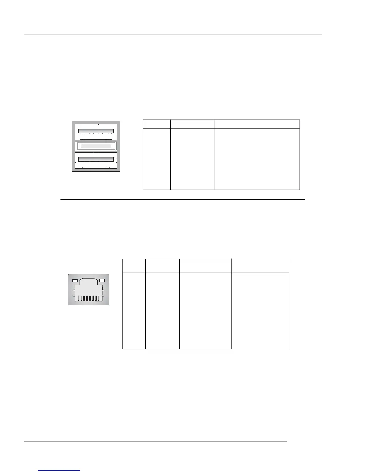
USB Connectors
The mainboard provides an OHCI (Open Host Controller Interface) Universal
Serial Bus root for attaching USB devices such as keyboard, mouse or other USB-
compatible devices. You can plug the USB device directly into the connector.
USB Ports
1 2 3 4
5 6 7 8
PIN SIGNAL DESCRIPTION
1 VCC +5V
2 -Data 0 Negative Data Channel 0
3 +Data0 Positive Data Channel 0
4 GND Ground
5 VCC +5V
6 -Data 1 Negative Data Channel 1
7 +Data 1 Positive Data Channel 1
8 GND Ground
USB Port Description
LAN (RJ-45) Jack
The mainboard provides 1 standard RJ-45 jack for connection to single Local
Area Network (LAN). This LAN enables data to be transferred at 1000Mbps (for
RTL8110S onlly), 100Mbps or 10Mbps. You can connect a network cable to it.
Pin Definition
PIN SIGNAL Description
(Gb/ Mb) for Gb LAN
1 D0P/ TDP Differential Pair 0+
2 D0N/ TDN Differential Pair 0-
3 D1P/ RDP Differential Pair 1+
4 D2P/ NC Differential Pair 2+
5 D2N/ NC Differential Pair 2-
6 D1N/ RDN Differential Pair 1-
7 D3P/ NC Differential Pair 3+
8 D3N/ NC Differential Pair 3-
RJ-45 LAN Jack
Description for
10/ 100 Mb LAN
Transmit Differential Pair
Transmit Differential Pair
Receive Differential Pair
Not Used
Not Used
Receive Differential Pair
Not Used
Not Used
 Loading...