2-15
Hardware Setup
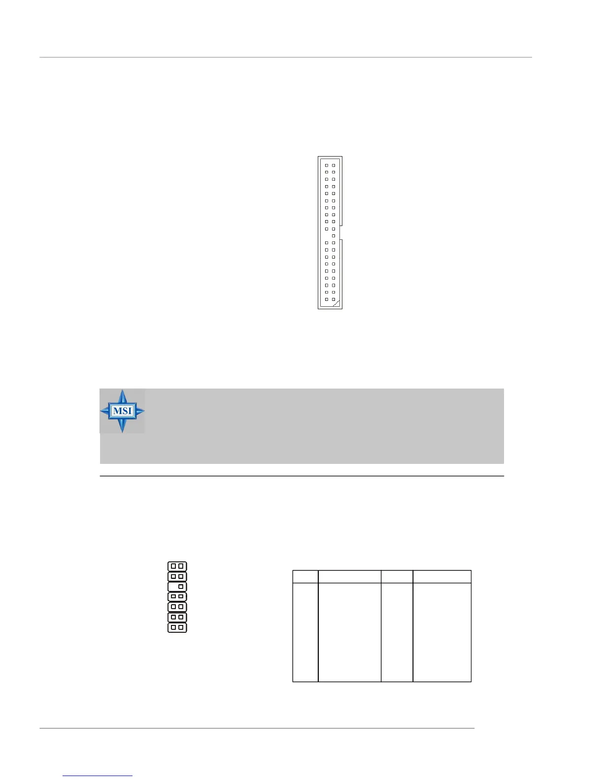
Hard Disk Connector: IDE1
The mainboard has one 32-bit Ultra DMA 66/100 IDE controller integrated in the
SourthBridge ICH6R/ICH6, which supports PIO & Bus Master operation modes and it
can connect up to two Ultra ATA drives.
IDE1 (Primary IDE Connector)
IDE1 can connect a Master and a Slave drive. You must configure second hard drive
to Slave mode by setting the jumper accordingly.
MSI Reminds You...
If you install two hard disks on cable, you must configure the second
drive to Slave mode by setting its jumper. Refer to the hard disk
documentation supplied by hard disk vendors for jumper setting
instructions.
IDE1 (blue)
FWH/LPC Debugging Pin Header: JLPC1
The pin header is for internal debugging only.
JLPC1
Pin Definition
PIN SIGNAL PIN SIGNAL
1 LCLK 2 Key (no pin)
3 LRST# 4 VCC3
5 LAD0 6 FID0_LRST
7 LAD1 8 VCC5
9 LAD2 10 Key (no pin)
11 LAD3 12 GND
13 LFRAME# 14 GND
13
14
21
 Loading...