2-17
Hardware Setup
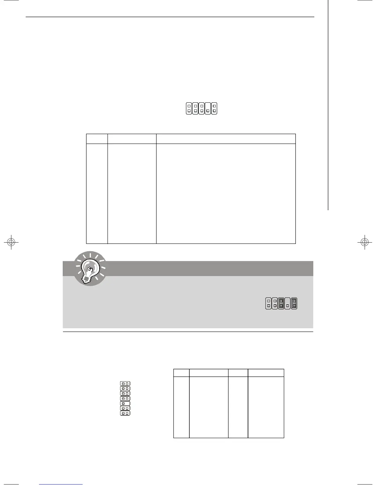
Front Panel Audio Connector: JAUD1
This connector allows you to connect the front panel audio and is compliant with
Intel
®
Front Panel I/O Connectivity Design Guide.
JAUD1
1
2
9
10
PIN SIGNAL DESCRIPTION
1 MIC_L Microphone - Left channel
2 GND Ground
3 MIC_R Microphone - Right channel
4 PRESENCE# Active low signal-signals BIOS that a High Definition Audio dongle
is connected to the analog header. PRESENCE# = 0 when a
High Definition Audio dongle is connected
5 LINE out_R Analog Port - Right channel
6 MIC_JD Jack detection return from front panel microphone JACK1
7 Front_JD Jack detection sense line from the High Definition Audio CODEC
jack detection resistor network
8 NC No control
9 LINE out_L Analog Port - Left channel
10 LINEout_JD Jack detection return from front panel JACK2
Pin Definition
Important
If you don’t want to connect to the front audio header, pins 5 &
6, 9 & 10 have to be jumpered in order to have signal output
directed to the rear audio ports. Otherwise, the Line-Out con-
nector on the back panel will not function.
5
6
10
9
Pin Definition
PIN SIGNAL PIN SIGNAL
1 LCLK 2 Key (no pin)
3 LRST# 4 VCC3
5 LAD0 6 FID0_LRST
7 LAD1 8 VCC5
9 LAD2 10 Key (no pin)
11 LAD3 12 GND
13 LFRAME# 14 GND
FWH/LPC Debugging connector: JLPC1
This connector is for internal debugging only.
JLPC1
13
14
2
1
7346v1.0-2-Hardware.p65 2007/3/6, 上午 11:5817
 Loading...