2-19
Hardware Setup
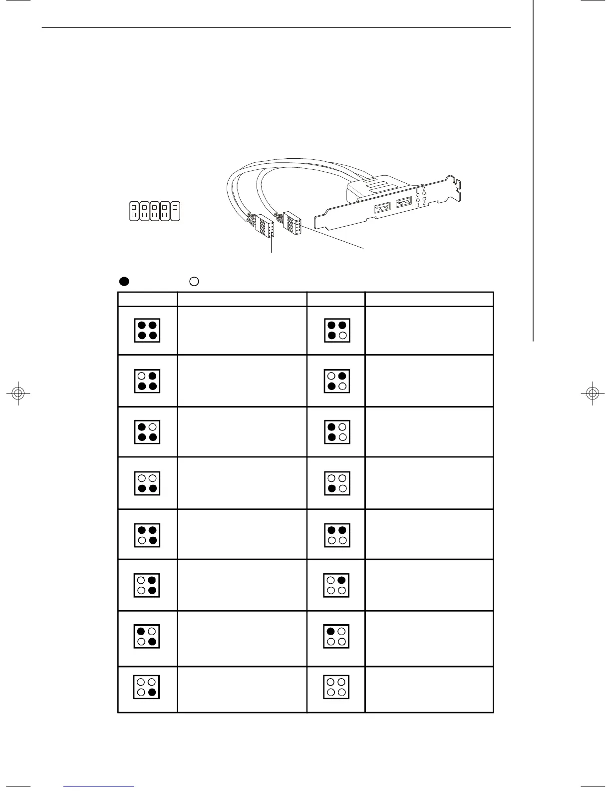
D-Bracket™ 2 Connector: JDB1
This connector is for you to connect to the D-Bracket™2 which integrates four LEDs
and USB ports. It allows users to identify system problems through 16 various com-
binations of LED signals.
1
9
2
10
DBG1
DBG2
DBG3
DBG4
Key
DBR1
DBR2
DBR3
DBR4
NC
BIOS Sign On
This will start showing information
about logo, processor brand name,
etc...
Testing Base and Extended Memory
Testing base memory from 240K to
640K and extended memory above
1MB using various patterns.
Assign Resources to all ISA.
Initializing Hard Drive Controller
This will initialize IDE drive and
controller.
Initializing Floppy Drive Controller
This will initialize Floppy Drive and
controller.
Boot Attempt
This will set low stack and boot via
INT 19h.
Operating System Booting
System Power ON
The D-LED will hang here if the
processor is damaged or not in-
stalled properly.
Initializing Keyboard Controller.
Testing VGA BIOS
This will start writing VGA sign-on
message to the screen.
Processor Initialization
This will show information regarding
the processor (like brand name, sys-
tem bus, etc...)
Testing RTC (Real Time Clock)
Description
Red
Green
LED Signal
1 2
3 4
1 2
3 4
1 2
3 4
1 2
3 4
1 2
3 4
1 2
3 4
1 2
3 4
1 2
3 4
DescriptionLED Signal
1 2
3 4
1 2
3 4
1 2
3 4
1 2
3 4
1 2
3 4
1 2
3 4
1 2
3 4
1 2
3 4
Early Chipset Initialization
Memory Detection Test
Testing onboard memory size. The
D-LED will hang if the memory mod-
ule is damaged or not installed
properly.
Decompressing BIOS image to RAM
for fast booting.
Initializing Video Interface
This will start detecting CPU clock,
checking type of video onboard. Then,
detect and initialize the video adapter.
D-Bracket™ 2
(Optional)
Connected to JDB1
Connected to USB connector
7346v1.0-2-Hardware.p65 2007/3/6, 上午 11:5819
 Loading...