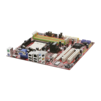
MS-7346 Mainboard
2-18
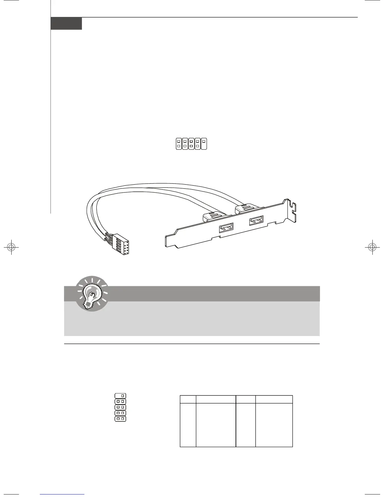
Front USB Connector: JUSB1 / JUSB2
This connector, compliant with Intel
®
I/O Connectivity Design Guide, is ideal for con-
necting high-speed USB interface peripherals such as USB HDD, digital cameras,
MP3 players, printers, modems and the like.
1
2
9
10
JUSB1/2
Important
Note that the pins of VCC and GND must be connected correctly to avoid
possible damage.
USB 2.0 Bracket
(Optional)
JSPI Debugging Pin Header: JSPI1
The pin header is for internal debugging only.
JSPI1 Pin Definition
PIN SIGNAL PIN SIGNAL
1 VCC3_SB 2 VCC3_SB
3 SPI_MISO 4 SPI_MOSI_F
5 SPI_CSO_F# 6 SPI_CLK_F
7 GND 8 GND
9 Reserved 10 NC
JSPI1
9
10
2
1
7346v1.0-2-Hardware.p65 2007/3/6, 上午 11:5818
 Loading...