2-10
Hardware Setup Industrial Computer Board
Hardware Setup Industrial Computer Board
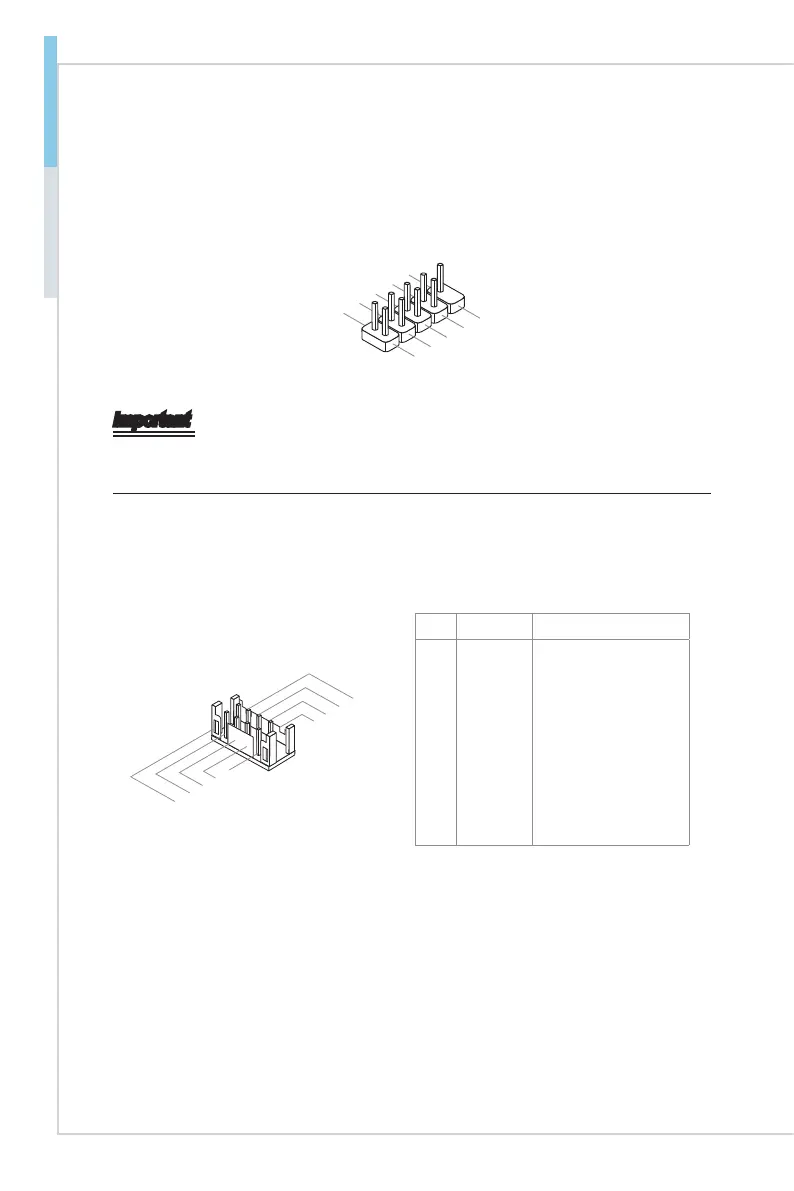
USB 2.0 Connector: JUSB1, JUSB2
This connector, compliant with Intel I/O Connectivity Design Guide, is ideal for con-
necting high-speed USB interface peripherals such as USB HDD, digital cameras,
MP3 players, printers, modems and the like.
1.VC
C
3.USB0
-
10.NC
5.USB0
+
7
.Ground
9.No
Pi
n
8
.Ground
6.USB1+
4.USB1-
2.VC
C
Important
Note that the pins of VCC and GND must be connected correctly to avoid possible
damage.
Serial Port Connector: COM2 ~ COM6
This connector is a 16550A high speed communications port that sends/receives 16
bytes FIFOs. You can attach a serial device to it.
8.CT
S
3.TX
D
1.DCD
6.DS
R
5.GN
D
4.DT
R
7.
RT
S
2.RX
D
9.RI
PIN SIGNAL DESCRIPTION
1
2
3
4
5
6
7
8
9
DCD
RXD
TXD
DTR
GND
DSR
RTS
CTS
RI
Data Carrier Detect
Receive Data
Transmit Data
Data Terminal Ready
Signal Ground
Data Set Ready
Request To Send
Clear To Send
Ring Indicate
 Loading...