Hardware Setup Industrial Computer Board
2-13
Hardware Setup Industrial Computer Board
Chassis Intrusion Pin Header: JCASE1
This connector connects to the chassis intrusion switch cable. If the computer
case is opened, the chassis intrusion mechanism will be activated. The system
will record this intrusion and a warning message will flash on screen. To clear the
warning, you must enter the BIOS utility and clear the record.
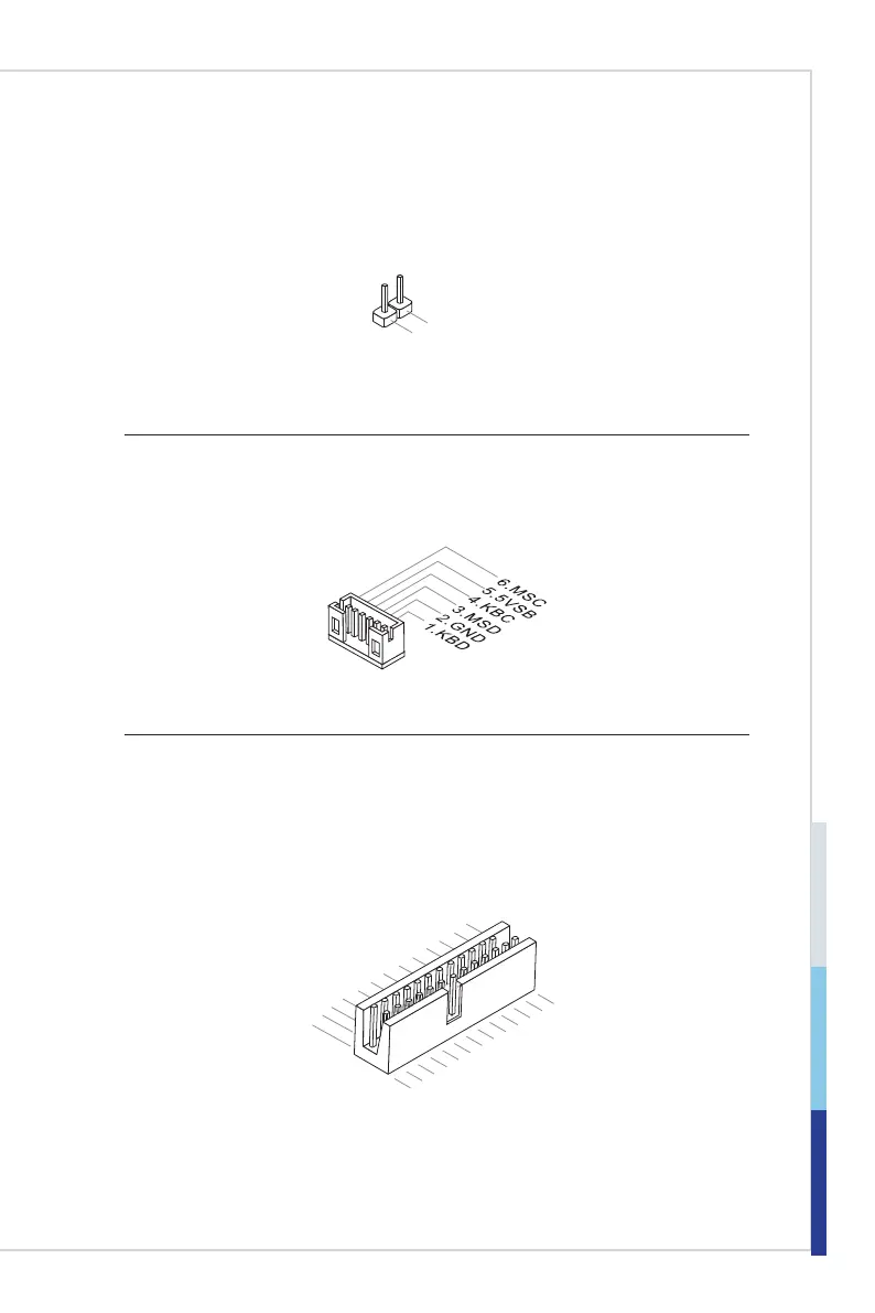
Keyboard/Mouse Connector: JKBMS1
This connector is provided to connect a keyboard and a mouse.
Parallel Port Connector: JLPT1
The mainboard provides a 26-pin header for connection to an optional parallel
port bracket. The parallel port is a standard printer port that supports Enhanced
Parallel Port (EPP) and Extended Capabilities Parallel Port (ECP) mode.
1.RSTB
#
3.PRND0
5.PRND1
7.PRND2
9.PRND3
11
.PRND4
13.PRND5
15.PRND6
17.PRND7
19.ACK#
21.BUSY
23.PE
25.SLCT
10.Ground
14.Ground
8.LPT_SLIN
#
12.Ground
6.PINIT#
4.ERR#
2.AFD#
24.Ground
22.Ground
26.No
Pin
20.Ground
18.Ground
16.Ground
 Loading...