2-20
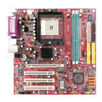
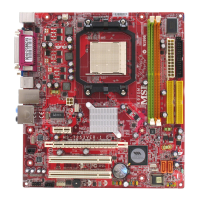
MS-7191 M-ATX Mainboard
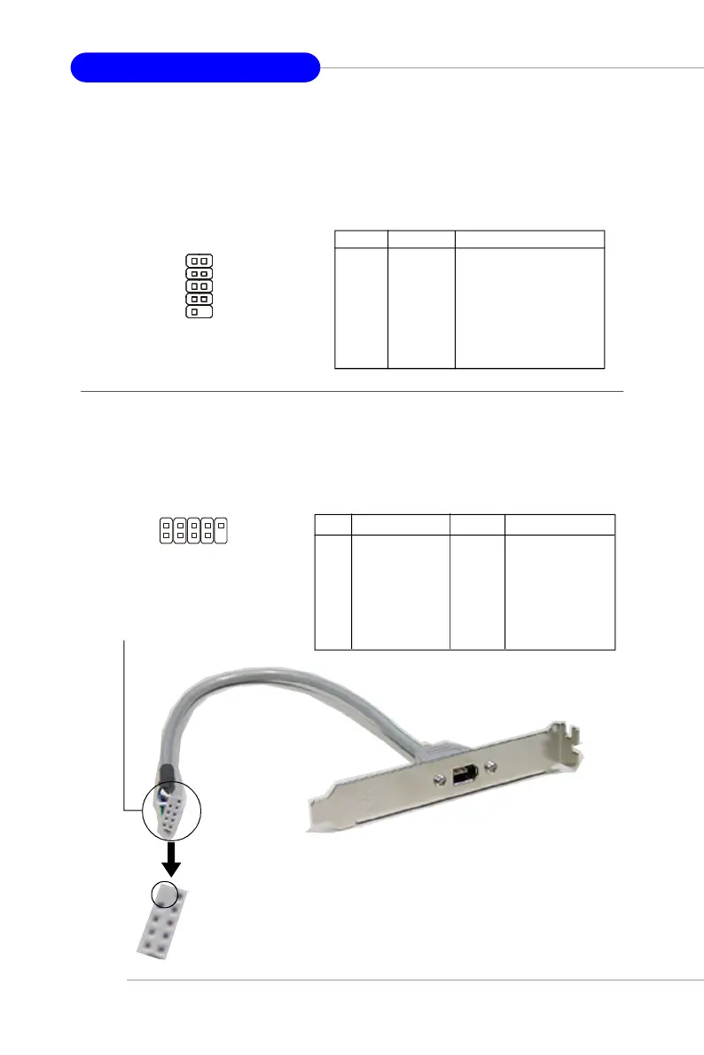
IEEE 1394 Connectors: J1394_1
The mainboard provides one 1394 pin header that allows you to connect IEEE
1394 ports via an external IEEE1394 bracket (optional).
Pin Definition
PIN SIGNAL PIN SIGNAL
1 TPA+ 2 TPA-
3 Ground 4 Ground
5 TPB+ 6 TPB-
7 Cable power 8 Cable power
9 Key (no pin) 10 Ground
Foolproof
design
Connected to J1394_1
(Green connector)
IEEE1394 Bracket (Optional)
J1394_1
1
2
9
10
Serial Port Header: JCOM1
The mainboard offers one 9-pin header as serial port. The port is a 16550A
high speed communication port that sends/receives 16 bytes FIFOs. You can attach
a serial mouse or other serial device directly to it.
Pin Definition
PIN SIGNAL DESCRIPTION
1 DCD Data Carry Detect
2 SIN Serial In or Receive Data
3 SOUT Serial Out or Transmit Data
4 DTR Data Terminal Ready)
5 GND Ground
6 DSR Data Set Ready
7 RTS Request To Send
8 CTS Clear To Send
9 RI Ring Indicate
JCOM1
1
5
6
9
 Loading...