EasyManuals Logo
Home>Multiplex>Remote Control>EUROPA mc 1010

Multiplex EUROPA mc 1010 User Manual

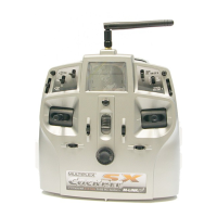
Multiplex EUROPA mc 1010
98 pages
To Next Page IconTo Next Page
To Previous Page IconTo Previous Page
Page #93 background imageLoading...
Page #93 background image
How
are
sticks
and
other
transmitter
controls
calibrated?
Before
you
carry
out the
calibration
process,
it
is
essential
to
check
that
the sticks,
adjustors
and switches
work
in
the
correct
sense,
ordirection.
1.
Switch
oft the
transmitter.
2.
Set
all transmitter
controls
tor
channels
1
to
6 to
centre
(sticks,
trims,
adjustors,
3-position
switches)
The
position
which
the
controls
are in
when
you
switch
on wath
the E
button
pressed
in will
be
stored
as the
centre
oosition.
3.
Press
the E
button,
hold
it in,
and
switch
on
the
transmitter
In
the display
the code numbers
1
to 6 will
all have
a dark
background.
4.
Calibrating
The
calibration
procedure
is
carrred
out
separatelv
for
each
axrs
ot each
stick. Thus
for
a EUROqA
mc 1005
two
processes
"re
required,
tot
the EUBO2A
mc 1010,
1020
and nautic
tour
orocesses.
For
each
stick
and
each
direction:
.
Move
the
trim to
one end-point (e.g.
left).
.
Hold
the
stick
at the
corresponding
end-point
for
about
one
second.
At
the
end-point
an arrow
will
appear in
the
display
(e.9.
lelt
/ forward).
.
Move
the
trim
to the
opposite
end-point.
.
Hold
the stick
at
the corresponding
end-point
for
about
one
second.
The
opposite
arrow
should now
appear in
the
display,
and the
dark
square
behind
the
code number
should
disappear.
For
every
other
transmitter
control
(slider,
switch)
which
is
connected
to
channels
1
to 6:
.
Hold
the
control
at one
end-point
for
about
one
second.
When
the end-point
is
reached
an arrow
will
aDpear in
the
dlsplay:
lefvforward
or righvback.
.
Move
the control
to the
opposite
end_point
and hold it
for
about
one second.
When
the
end-point
ls reached
the
opposite
arrow
will
appear
in
the display.
Once
the
electronics
have
detected
the two
end-points.
the
oarK
square
behind
the
code number
will
disaooear.
It
the
dark
square
does not
disappear,
check
that
the
plug
is
engaged
correclly
on the
contacts,
then repeat
the calibration
process.
When
the calibration process
is
complete,
none
ot the
code
numbers
lo
which
controls
are
connected
should have
dark
backgrounds.
5. End
the
process,
return
to the
Status
display
Press
the E
button.
The
calibration
is
complete,
and
the Status
display
appears.
How
is
the
stick ratchet
installed?
lf
you
want
one
stick function
to,,stay
put',,
i.e.
not return
to neurral
automatically,
you
can install
a
ratchet
instead
of
the
return
spring.
Open
the transmitter
and remove
the
return
spring
and
neutratising
ärm for
the
stick axis
you
wish
to
convert.
Fit
the
ratchet
spring
as shown
in
the
diagram
on the right.
The
stillness
of
the
ratchet
varies
according
to the
tightness
ot
the screw
holdino
the
ratchet
spring.
lEEl,
,u
wH
ArA
___!.
-
\_
ry
tr
re[p
,42,
s
q,
v
7
left/fotuard
/
right/back
Fig.29:lnsta
ing
the
stick
rctchet
Ratchet
G8.27
Manual
EUROPA
mc

Table of Contents

Questions and Answers:

Question and Answer IconNeed help?

Do you have a question about the Multiplex EUROPA mc 1010 and is the answer not in the manual?

Multiplex EUROPA mc 1010 Specifications

General IconGeneral
BrandMultiplex
ModelEUROPA mc 1010
CategoryRemote Control
LanguageEnglish

Related product manuals