1
14
15
2
3
4
5
6
7
8
9
10
9
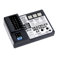
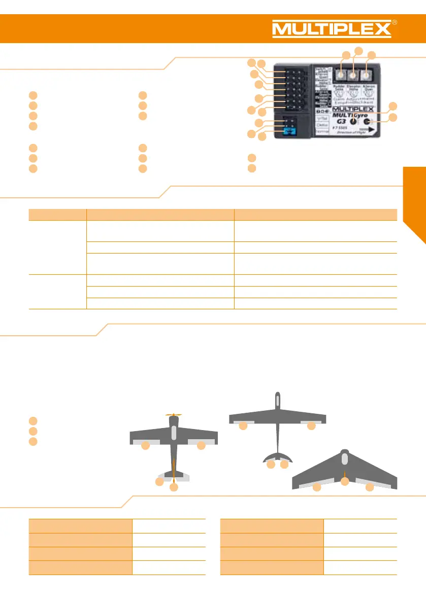
2. Overview MULTIGyro G3
3. Features
2.1 Overview LED display
“IN” area Model type selection (jumper)
1
Flight mode changeover switch
8
J1 – V-tail
2
Aileron
9
J2 – Delta wing or ying wing
3
Elevator
10
J3 – Standard aircraft model
4
Rudder
“OUT” area
Gyro gain adjustment
5
Aileron
11
Potentiometer rudder
6
Elevator
12
Potentiometer elevator
7
Rudder
13
Potentiometer aileron
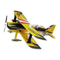
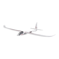
Supported model types:
Standard
aircraft
Aircraft with
a V-tail
Delta wing or
flying wing
4. Technical data
11
2
3 1
3
2
1 1
2 3
LED display
14
Red LED
15
Blue LED
Status LED display Description
Initialisation The blue and red LEDs ash rapidly for three
seconds after switching on the gyro.
Initialised. Do not move the aircraft until initialisation
has been completed!
Blue LED ashes after initialisation. Initialisation successful.
Red LED ashes rapidly after initialisation. Initialisation failed. Undened model type. Check the
adjustments J 1-2-3.
Operation Blue LED illuminated permanently. Standard mode. Ready for ight.
Red LED illuminated permanently. Heading hold mode. Ready for ight.
Both LEDs are off. Gyro is deactivated. Ready for ight.
· It is possible to toggle between three flight modes while
your model is airborne: 1. Off / 2. Standard / 3. Heading hold
· MULTIGyro G3 supports three model types:
1. Standard aircraft / 2. Delta wing or flying wing /
3. Aircraft with a V-tail
· Specially optimised for 3D flight.
· Independent gyro adjustment and gyro reversing for each
channel.
·
Small and lightweight, thus also suitable for smaller
aircraft.
1
Aileron servo
2
Elevator servo
3
Rudder servo
Voltage range 5 - 6V DC
PWM output 50Hz, or 20ms
PWM signal 1520±500µs
Full scale range 970~2070µs
Gyro sample rate 1KHz
Operating temperature -40°C to 85°C
Dimensions 47 x 33 x 14 mm
Weight 11 g
11
12
13
 Loading...