2202MYJE-MY-C8-N_2018.02.
Chapter 5 Maintenance and Inspection
Compound 2-stage Screw Compressor 3225**C 5.4 Disassembly and Inspection
5-16
○ High-stage
Regarding the high-stage capacity control, the 3225*SC and 3225*LC types have the load
indication of 30 to 100% while the model 3225*LC has the load indication 0 to 100%. Accordingly,
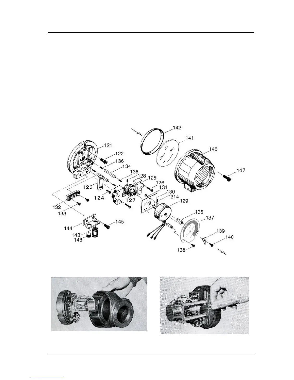
the dial [137] and micro-switch cam [127] of the types *SC and *MC are for the indication of 30 to
100% while the type *LC has the standard dial and micro-switch cam for the 0 to 100% indication,
according to the standard (200UD/G) specification. Otherwise, the mechanism of the indicator is the
same between all types.
a) By removing the three hexagon socket head cap screws [147] that are used to fasten the
indicator cover [146], the cover can be removed.
b) The indicator cover will be removed with the glass [141] and spacer [142] attached. While the
glass and spacer are glued, be careful not to drop these as they may be separated from the
cover.
c) Remove the wiring.
Figure 5-3 Exploded View of the Standard High-stage Indicator for 3225**C
 Loading...