2202MYJE-MY-C8-N_2018.02.
Chapter 5 Maintenance and Inspection
Compound 2-stage Screw Compressor 3225**C 5.4 Disassembly and Inspection
5-31
5.4.11 Low-stage Suction Cover and Side Bearings
Similarly to the case of the high-stage, the lock nut fastening the thrust bearing should be loosened
before removing the suction cover.
5.4.11.1 Disassembly
a) Remove the hexagon head bolts [45-1] fastening the thrust bearing gland [43-1] and O-ring [150].
As conical spring washers [46-1] are used together, be careful not to lose them.
b) Unbend the tooth of the lock washer [40-1], and loosen the lock nut [39-1].
c) Loosen and remove the hexagon socket head cap screws [2-1] securing the suction cover [5-1] to
the main rotor casing [1-1].
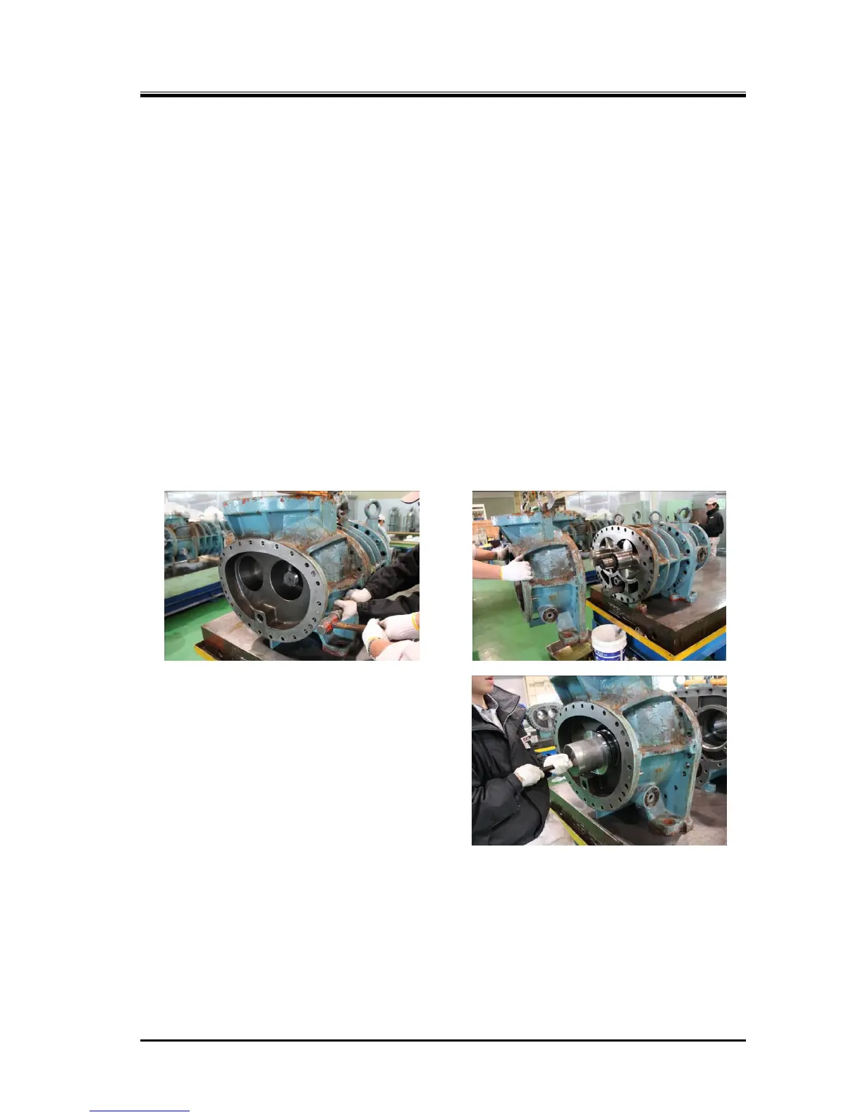
d) Drive in the alignment pins [3-1] to the main rotor casing side as shown in Photo 35. If it is not
feasible, screw in suitable bolts to the jacking screw holes on the flange to push the suction cover
evenly.
e) At this time, the alignment pins will also be disengaged. Even after the alignment pins are
disengaged, as the rotor shaft and side bearing are still engaged together, pull out the suction cover
carefully along the shaft axis (Photo 36).
f) Remove the snap ring [29-1] holding the side bearing using internal snap ring pliers.
g) Either push out the side bearing from the main rotor casing side using some block or pull it out using
a special tool such as shown in Photo 037. For the details of the special tool, refer to Section 5.5.2
in this chapter.
 Loading...