2202MYJE-MY-C8-N_2018.02.
Chapter 5 Maintenance and Inspection
Compound 2-stage Screw Compressor 3225**C 5.4 Disassembly and Inspection
5-32
5.4.12 Thrust Bearing Block
5.4.12.1 Disassembly of High-stage Thrust Bearing Block
Table 5-6 Component Parts of the High-stage
Thrust Bearing Block
Thrust bearing alignment spacer (2)
Conical spring washer (2)
Torsional slip washer (2)
The high-stage thrust bearing block of 3225**C has no spacer for the thrust bearing outer race. While
the thrust bearing outer race spacer is used to support (i.e., ensure a sufficient support width for) the
outer race of the thrust bearing, 250 or higher models use no spacer for the thrust bearing outer race
because the case (bearing head) side has sufficient margin to the support it.
a) Remove the lock nut [39-2] that has been loosened. Then, remove the torsional slip washer [237-2],
lock washer [40-2], and thrust washer [250-2].
b) The clearance fit is applied to two gaps between the outer race of the thrust bearing and the bearing
head, between the inner race of the thrust bearing and the rotor shaft.
Prepare a 1 or 2 mm diameter aluminum wire, make the tip of the wire flat by hammering, and
slightly bend the tip to make a hook. Then, insert the tip of the wire between the outer race and the
ball retainer of the thrust bearing [38-2] to hook and pull out the bearing. In this way, the bearing can
be easily removed.
c) The whole thrust bearing will be removed helped by the surface tension of the oil on the side face.
If you have failed to remove the whole bearing at once, put the components in the order of the
removal.
d) Inside the thrust bearing is an alignment spacer [42-2] for the inner race on the rotor shaft side. The
M rotor side has a marking of "M", and the F rotor side has a marking of "F".
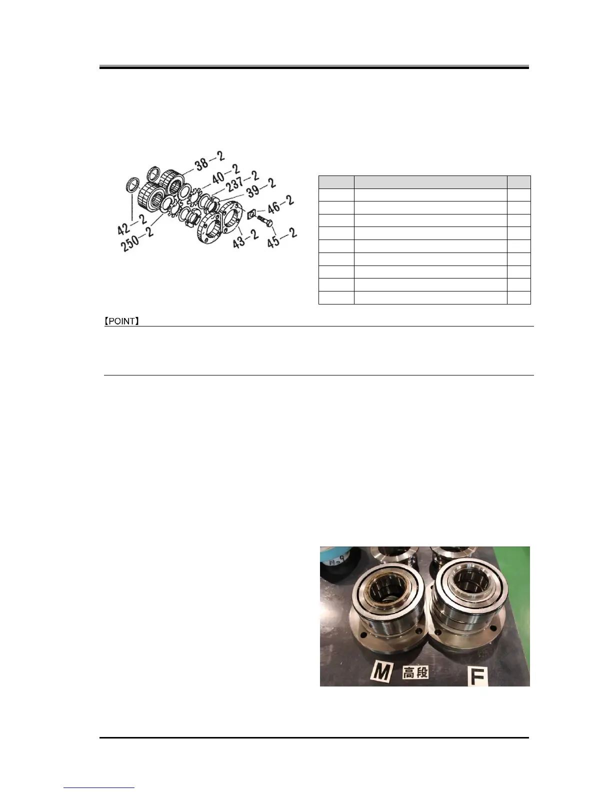
Neatly arrange the parts removed, i.e., the
thrust bearing gland, thrust washer, thrust
bearing, and thrust bearing alignment spacer,
separately for the M rotor and F rotor as shown
in Photo 040.
You must be very careful because if an
assembly error is made to result in a wrong
combination of parts after failing to neatly
arranging and separating the parts, it can lead
to performance degradation and/or dragging
accident due to overheating caused by being
too narrow clearance, for example.
Figure 5-11 High-stage Thrust Bearing Block
 Loading...