Chapter 5 Maintenance and Inspection
UD-series Screw Compressor 5.5 Reassembly
5-50
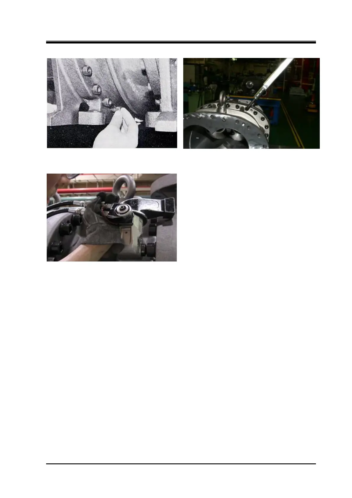
Tightening the bolts at the bottom of the rotor
casing
Tightening the upper bolt
Bolt tightening with a hydraulic wrench (320-400UD)
i) Check the movement of the unloader slide valve, and check that the M rotor shaft can be
turned by hand.
5.5.5 Balance Piston Sleeve
a) Install the balance piston part into the suction cover as follows.
The 125 has no built-in balance piston sleeve.
First, install the stop ring (part number 37).
Next, install the "O" ring spacer (part number 36), "O" ring (part number 35), balance piston
sleeve (part number 33), and stop ring in that order.
Finally, the stop ring to be assembled is
pushed outward by the "O" ring of the balance piston sleeve, so it enters the groove while
pushing it in.
When operating the above work, locking the balance piston sleeve from rotating by using
following method.
■Type1 (160~250SUD/MUD/LUD/SG/MG/LG/LLG)
Screw the hexagon socket set screw (Part No. 34) into the suction cover from the M rotor
side, and attach the hexagon socket set screw from the F rotor side.
■Type2 (320SUD/MUD/LUD/SU/MU/LU)
Fit the pin on the outer diameter of the balance piston sleeve into the groove on the suction
cover.
 Loading...

