Chapter 7 Related Documents
UD-series Screw Compressor 7.7 Gaskets Used
7-39
7.7 Gaskets Used
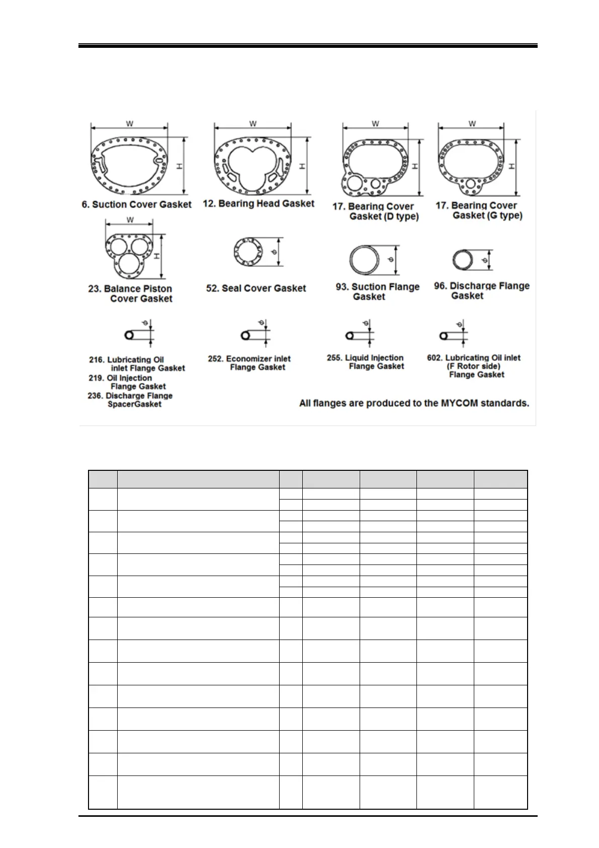
Figure 7-9
Gaskets Used
Table 7-19 Gasket Size (㎜)
P/N Location 160 200 250 320
6 Suction Cover
12 Bearing Head
17
17
23 Balance Piston Cover
52
Seal Cover
Φ 140 170 200 250
93 Suction Flange Φ
96 Discharge Flange Φ
216 Lubricating Oil inlet Flange Φ
―
219 Oil Injection Flange Φ
― ― ―
236 Discharge Flange Spacer Φ
252 Economizer Flange Φ
255 Liquid injection Flange Φ
602
Lubricating Oil (for F Rotor side
Bearing) inlet Flange
Φ
― ―
(20A)
 Loading...

