Chapter 2 Compressor Specifications and Structure
UD-series Screw Compressor 2.4 Compressor Structure and Mechanism
2-10
2.4 Compressor Structure and Mechanism
2.4.1 Overview of UD-series Screw Compressor
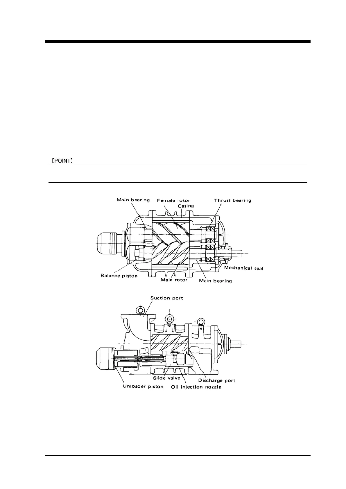
UD-series Screw Compressors are rotary compressors falling into the category of the positive
displacement compressor. The compressor sucks refrigerant gas into a cavity, gradually reduces the
volume of the cavity, and discharge the refrigerant as a high-pressure gas. More specifically, a sealed
cavity is formed by a casing and a pair of intermeshing rotors (called the male = M and female = F
rotors) in the casing. The rotors are different in lead and number of screw lobes. The volume of the
sealed cavity gets reduced as the rotors rotate. The gas trapped in the cavity is thus compressed
before it is discharged.
In the UD-series, the robe profile of the rotor also adopts an O profile with little leakage to improve
compression efficiency. In addition, the UD-series compressors employ O-profile screw lobes for the
rotors, which minimize leaks and thus enhance the compression efficiency.
For names and positions of each part of the compressor, refer to Section 7.1 "Exploded Views,
Sectional Views ", and Section 7.2 "Parts Configuration Table" in this manual Chapter 7.
Figure 2-4 Compressor Structure
 Loading...

