Chapter 5 Maintenance and Inspection
UD-series Screw Compressor 5.4 Disassembly and Inspection
5-33
Disassembly
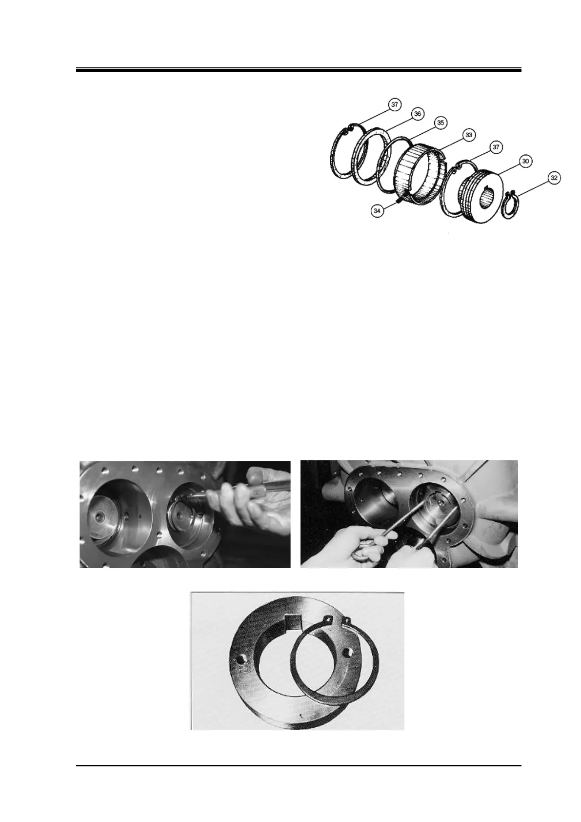
Disassembly of balance piston and balance piston sleeve
a) Remove the stop ring (part number 37) that secures the balance piston (part number 30) to
the shaft with the stop ring pliers.
b) Screw the accessory eye bolt into the balance piston and pull it out parallel to the axis.
The rotor shaft remains with the balance piston key (part number 31) embedded, but does not
need to be removed.
Removing Balance Piston retaining ring Pull out the Balance Piston
Balance piston
The screw compressor is structurally of the two
rotors M and F, and the M rotor rotates 1.5 times
more than the F rotor because the thrust caused
by the drive revolution of the M rotor and the
thrust caused by the difference in the gas
pressure are applied. If the same thrust bearing is
used, the life of the M rotor side will be shortened
remarkably. Therefore, a piston is installed at the
tip of the M rotor to apply hydraulic pressure in the
direction to cancel the thrust load.
This is the balance piston (part number 30).
The balance piston rotates with a narrow
clearance from the balance piston sleeve (part
Figure 5-16 Development view of the Balance Piston
 Loading...

