EasyManuals Logo
Home>mycom>Air Compressor>UD Series

mycom UD Series User Manual

Default Icon
179 pages
To Next Page IconTo Next Page
To Previous Page IconTo Previous Page
Page #45 background imageLoading...
Page #45 background image
Chapter 3 Installation
UD-series Screw Compressor 3.2 Installation Works
3-5
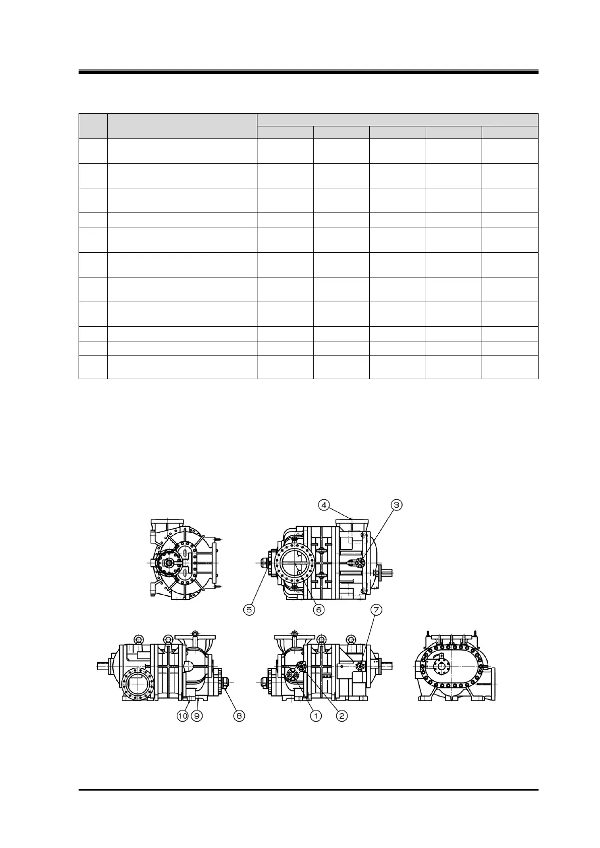
Table 3-2 Connecting Port of Compressor (125 320, Cast steel case)
No.
Item
Rotor diameter
125
160
200
250
320
1
Connecting port for liquid
injection 1
2
Connecting port for liquid
injection 2
3 Discharge gas outlettype D
ANSI #300
3”
ANSI #300
3”
ANSI #300
5”
ANSI #300
6”
ANSI #300
8”
4
Unloader control
decrease
NPT 1/4
NPT 1/4
NPT 3/8
NPT 3/8
NPT 3/8
5 Suction gas inlet
ANSI #300
4”
ANSI #300
5”
ANSI #300
6”
ANSI #300
10”
ANSI #300
14”
6
Lubricating oil main supply port
journal
NPT 3/8
ANSI #300
1/2”
ANSI #300
3/4”
ANSI #300
1”
ANSI #300
1 1/2”
7 Economizer connecting port
ANSI #300
1 1/2”
8
Control wiring connector for
indicator
2-PF 3/4 2-PF 3/4 2-PF 3/4 2-PF 3/4 2-PF 3/4
9
Unloader control
increase
NPT 1/4
NPT 3/8
NPT 3/8
NPT 1/2
NPT 1/2
10
Oil drain port
NPT 3/8
NPT 3/8
NPT 1/2
NPT 1/2
NPT 1/2
11 Oil injection port NPT 3/8 NPT 3/8
ANSI #300
1/2”
ANSI #300
1/2”
ANSI #300
1”
Please contact us for the blank size.
It may differ from the above table. Please check the figure for details.
Figure 3-3 Connecting Port of Compressor
400

Table of Contents

Questions and Answers:

Question and Answer IconNeed help?

Do you have a question about the mycom UD Series and is the answer not in the manual?

mycom UD Series Specifications

General IconGeneral
Brandmycom
ModelUD Series
CategoryAir Compressor
LanguageEnglish

Related product manuals