NAPCO Gemini C-Series Control Panel Installation Instructions--Volume 2
Installation Instructions, Volume 2 Page 67
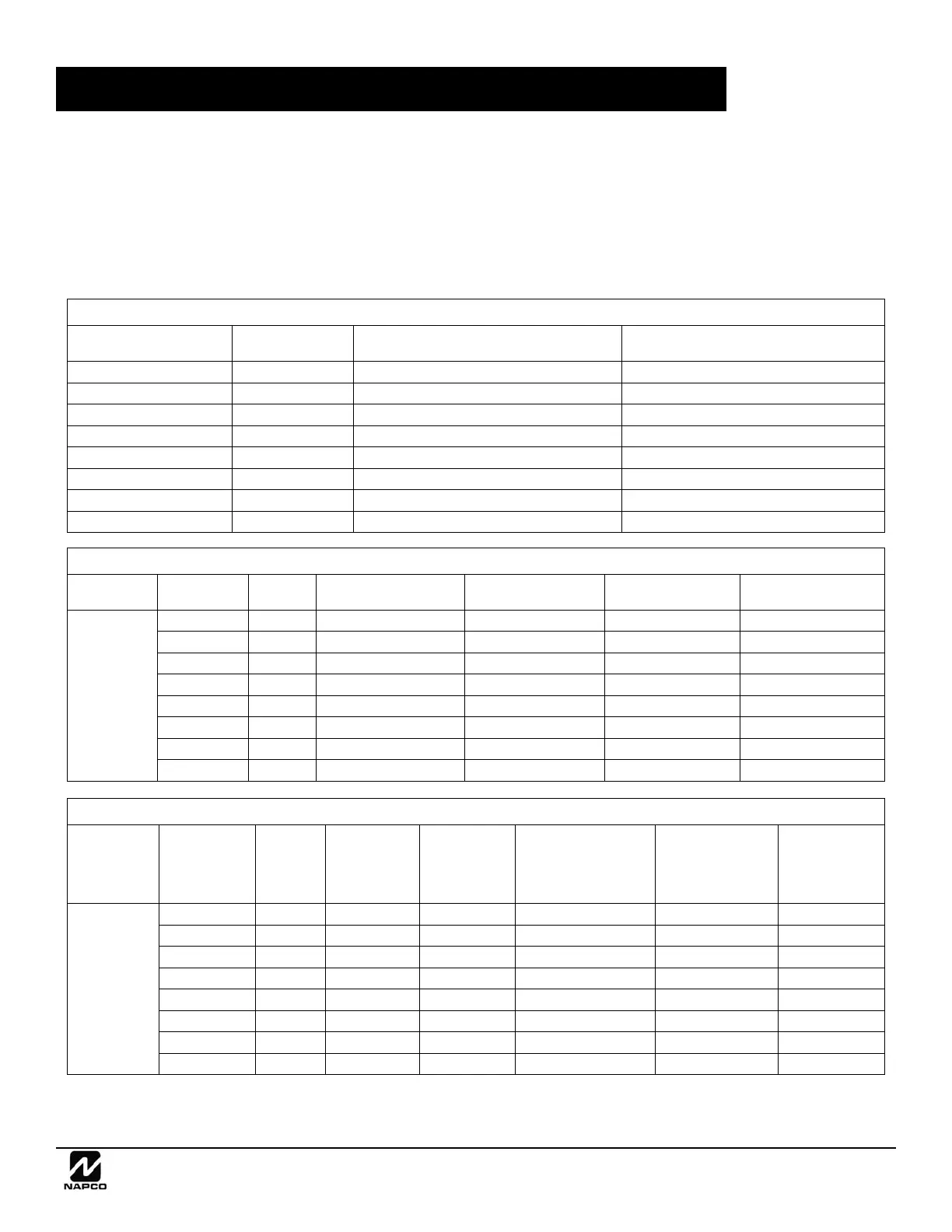
BATTERY STANDBY CURRENT
MAXIMUM STANDBY CURRENT (Fire Only with GEMC-PS24V7A)
Batteries Used
Total
24V AH
Maximum Available 24V Standby Current (mA) Maximum 24V Alarm + Standby Current
2 12V 7AH 7 204 3.5A
2 12V 8AH 8 240 4A
4 12V 7AH 14 455 7A
4 12V 8AH 16 530 7A
6 12V 7AH 21 717 7A
6 12V 8AH 24 830 7A
8 12V 7AH 28 980 7A
8 12V 8AH 32 1100 7A
Configuration Batteries Used
Total
24V AH
Maximum Available 24V
Standby Current (mA)
Maximum Available 12V
Standby Current (mA)
Maximum 12V Standby +
Alarm Current
Maximum 24V Alarm+
Standby Current
Fire Only with
GEMC-
PS24V4A
2 12V 7AH 7 154 225 2.5A 3.5A
2 12V 8AH 8 190 278 2.5A 4A
4 12V 7AH 14 415 606 2.5A 4A
4 12V 8AH 16 490 716 2.5A 4A
6 12V 7AH 21 678 989 2.5A 4A
6 12V 8AH 24 790 1154 2.5A 4A
8 12V 7AH 28 940 1373 2.5A 4A
8 12V 8AH 32 1100 1400 2.5A 4A
MAXIMUM STANDBY CURRENT (Fire Only with GEMC-PS24V4A )
Configuration Batteries Used
Total
24V AH
Maximum Avail-
able 24V Standby
Current (mA)
Maximum Avail-
able 12V Standby
Current (mA)
Maximum
Fire and Burglary
12V Standby + Alarm
Current
Maximum 24V
Alarm+ Standby
Current
Maximum Available
Burg 12V 4.5 Hour
Standby Current
(Rated Maximum =
750mA)
Fire with
GEMC-
PS24V7A and
GEMC-BM
2 12V 7AH 7 154 225 2.5A 3.5A 0.750
2 12V 8AH 8 190 278 2.5A 4A 0.750
4 12V 7AH 14 405 591 2.5A 7A 0.750
4 12V 8AH 16 480 700 2.5A 7A 0.750
6 12V 7AH 21 667 974 2.5A 7A 0.750
6 12V 8AH 24 780 1138 2.5A 7A 0.750
8 12V 7AH 28 930 1357 2.5A 7A 0.750
8 12V 8AH 32 1100 1400 2.5A 7A 0.750
MAXIMUM STANDBY CURRENT (Fire with GEMC-PS24V7A and GEMC-BM)
Notes: 24V standby current must be reduced by .68 times the amount of 12V standby current used.
12V standby current must be reduced by 1.46 times the amount of 24V standby current used.
24V standby + alarm current must be reduced by .68 times the amount of 12V standby + alarm current used.
All values are calculated used 10% derating factor except for the 32AH configuration, that was evaluated through test.
In addition to the charts that follow, PCD-Windows Quickloader download software can be used to provide the standby current require-
ment with the System Current Calculator utility (click Tools, System Current Calculator). To calculate the Standby Battery re-
quirements for the system:
1. Create the account in the PCD-Windows Quickloader.
2. Program all peripherals used on the system.
3. Open the "System Current Calculator" utility.
4. Complete all fields within each tab of the utility.
5. Use the resultant "24V Standby Current", "12V Standby Current", "24V Standby + Alarm Current", and "12V Standby +
Alarm Current" and the associated standby battery charts provided below to determine the required battery configuration.
continued
 Loading...