Chapter 2 Installing Compact FieldPoint Hardware and Software
© National Instruments Corporation 2-15 cFP-20xx and cFP-BP-x User Manual
Installing Connector Blocks on the Backplane
In order to connect I/O modules to input signals or to external loads, you
need to install a cFP-CB-x connector block or other connectivity accessory
for each I/O module on the backplane. Use the connector socket to the right
of each I/O module socket.
1. Align the captive screws on the connector block with the holes on the
backplane. The shape of the I/O connector on the connector block
prevents backward insertion.
2. Press firmly to seat the connector block on the backplane.
3. Using a number 2 Phillips screwdriver with a shank of at least 64 mm
(2.5 in.) length, tighten the captive screws to 1.1 N ⋅ m (10 lb ⋅ in.) of
torque. The nylon coating on the screws prevents them from loosening.
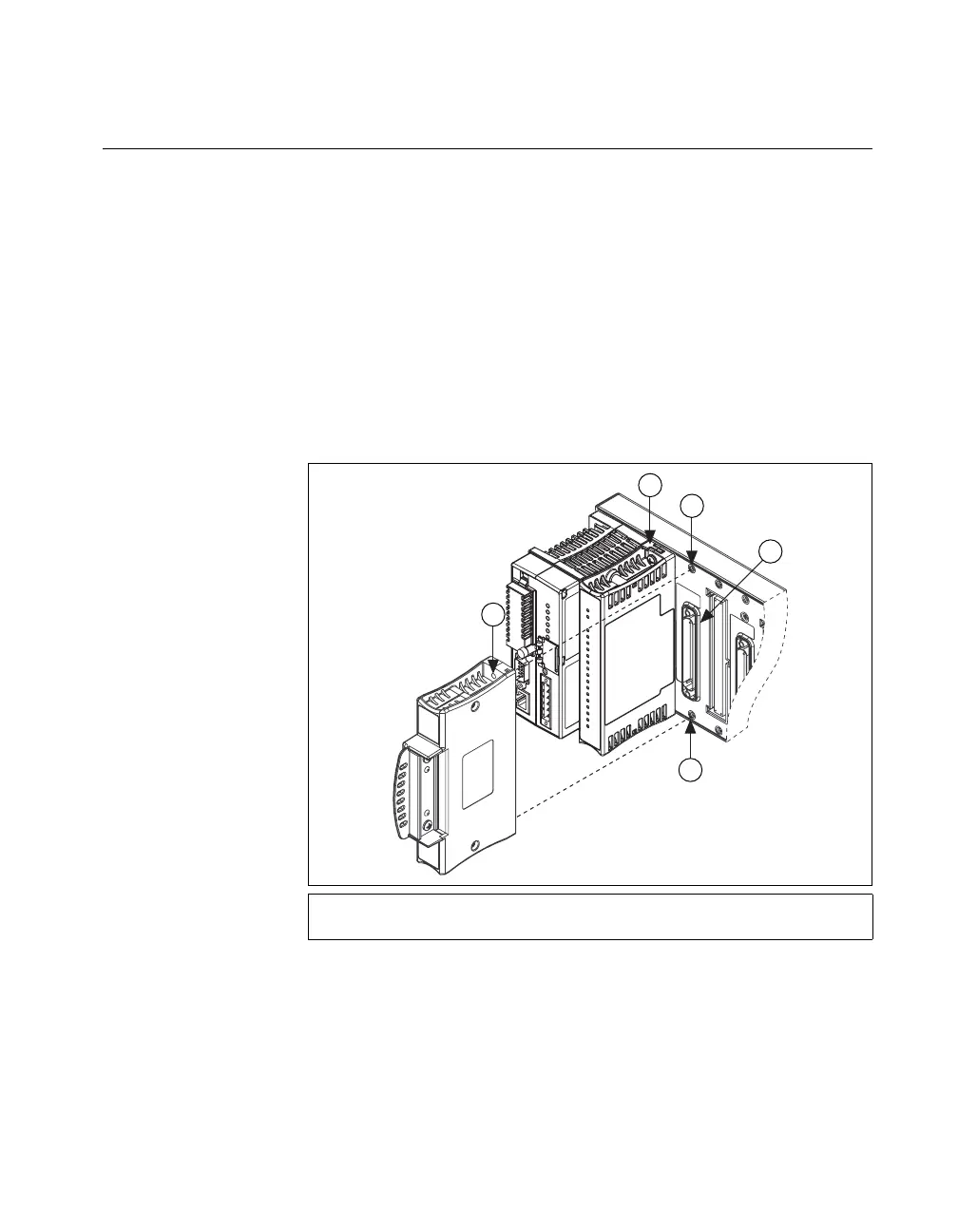
Figure 2-14. Installing a cFP-CB-x Connector Block
4. Repeat this procedure to install additional connector blocks on the
backplane.
1cFP-CB-x Connector Block
2 cFP I/O Module
3Screw Holes
4 Connector Slot
3
4
3
1
2
 Loading...