Chapter 3 Feature Descriptions
© National Instruments Corporation 3-3 cFP-20xx and cFP-BP-x User Manual
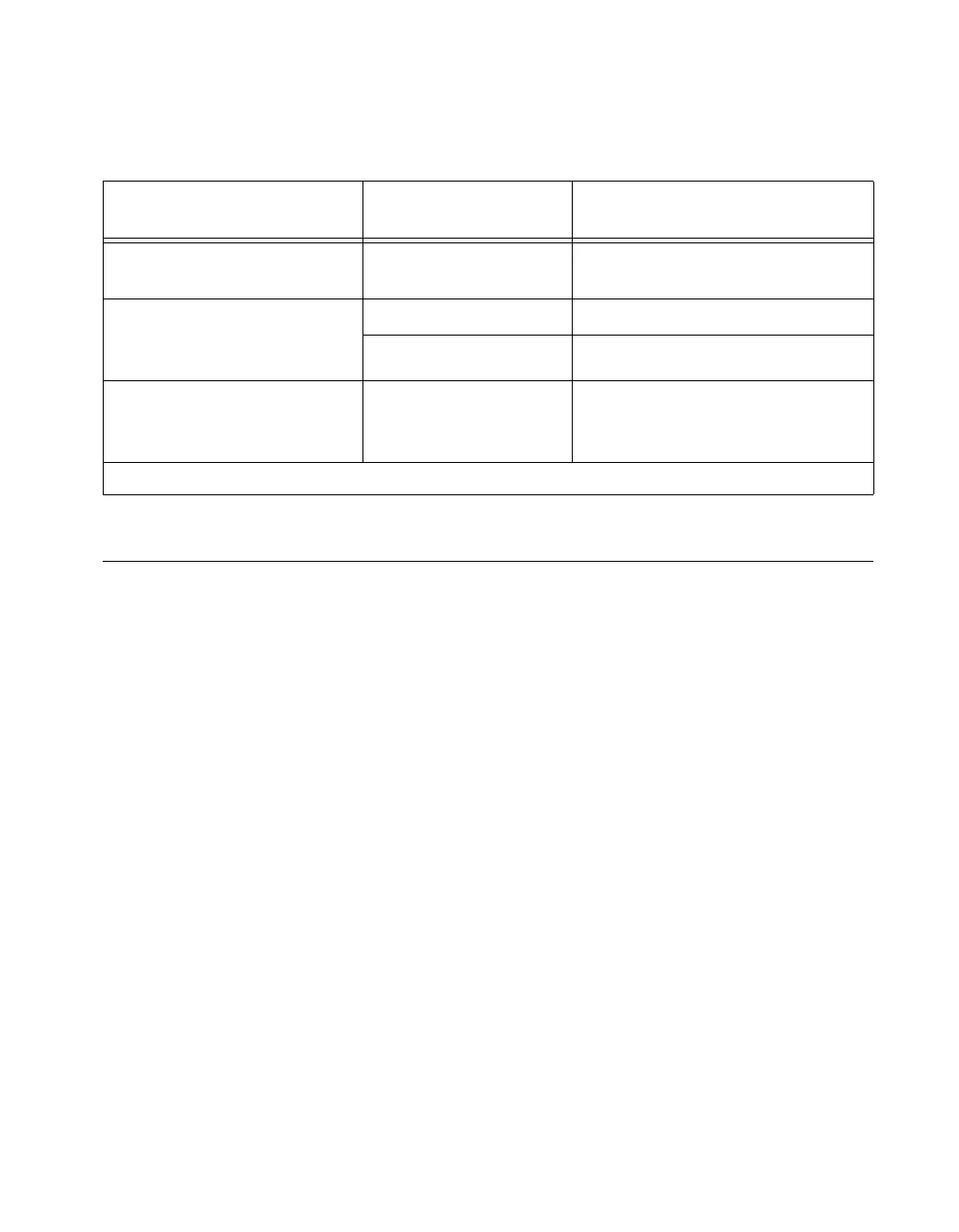
Table 3-1 shows how modules are configured after hot swapping.
LED Indicators
The cFP-20xx has several LEDs to indicate status information.
POWER LED
The green POWER LED is lit while the cFP-20xx is powered on.
This LED indicates that the power supply connected to the cFP-20xx is
acceptable, and that the cFP-20xx is supplying power to the I/O modules.
STATUS LED
The red STATUS LED is off in normal operation mode. The cFP-20xx
indicates specific error conditions by flashing STATUS a specific number
of times. Refer to the STATUS LED Error Indications section of
Appendix A, Troubleshooting, for more information about STATUS
LED error indications.
LINK ACT LED
The yellow LINK ACT LED blinks when the cFP-20xx receives data from
or transmits data to the Ethernet. Unrelated network activity causes this
LED to blink occasionally even when the cFP-20xx is inactive.
Table 3-1. Module Configuration Results after Hot Swapping
Replacement
Module
Factory Configuration
Checked?
1
Replacement Module
Configuration after Hot Swapping
Compatible with the removed
module
Yes o r No Same as the removed module
Incompatible with the removed
module but compatible with the
stored configuration
No Same as the stored configuration
Yes Factory default configuration
Incompatible with the removed
module and incompatible with
the stored configuration
Yes o r No Factory default configuration
1
The factory configuration checkbox is on the Bank Configuration tab in MAX.
 Loading...