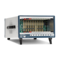
Chapter 2 Installation and Configuration
NI PXI-1042 Series User Manual 2-8 ni.com
Power Switch LED Indicator
The chassis power switch has an integrated LED. This LED indicates one
of three different conditions:
• If the power switch LED is steady green (not flashing), the chassis is
powered on and operating normally.
• If the power switch LED is flashing green, the air-intake temperature
has exceeded the chassis operating range.
• If the power switch LED is flashing red, the power supply outputs are
not within voltage regulation requirements.
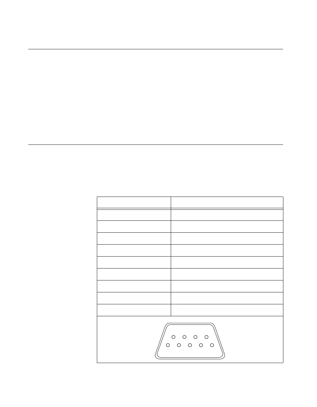
Remote Voltage Monitoring and Control
The PXI-1042 Series chassis support remote voltage monitoring and
inhibiting through a male 9-pin D-SUB (DB-9) connector located on the
rear panel. Table 2-1 shows the pinout of the 9-pin D-SUB (DB-9)
connector.
Table 2-1. Remote Inhibit and Voltage Monitoring Connector Pinout
DB-9 Pin Signal
1 Logic Ground
2 +5 VDC
3 Reserved
4 +3.3 VDC
5 Inhibit (Active Low)
6 +12 VDC
7 Reserved
8 –12 VDC
9 Logic Ground
1
2
3
4
5
6
978

 Loading...