© National Instruments | 3-3
RMX Programmable Power Supplies User Manual
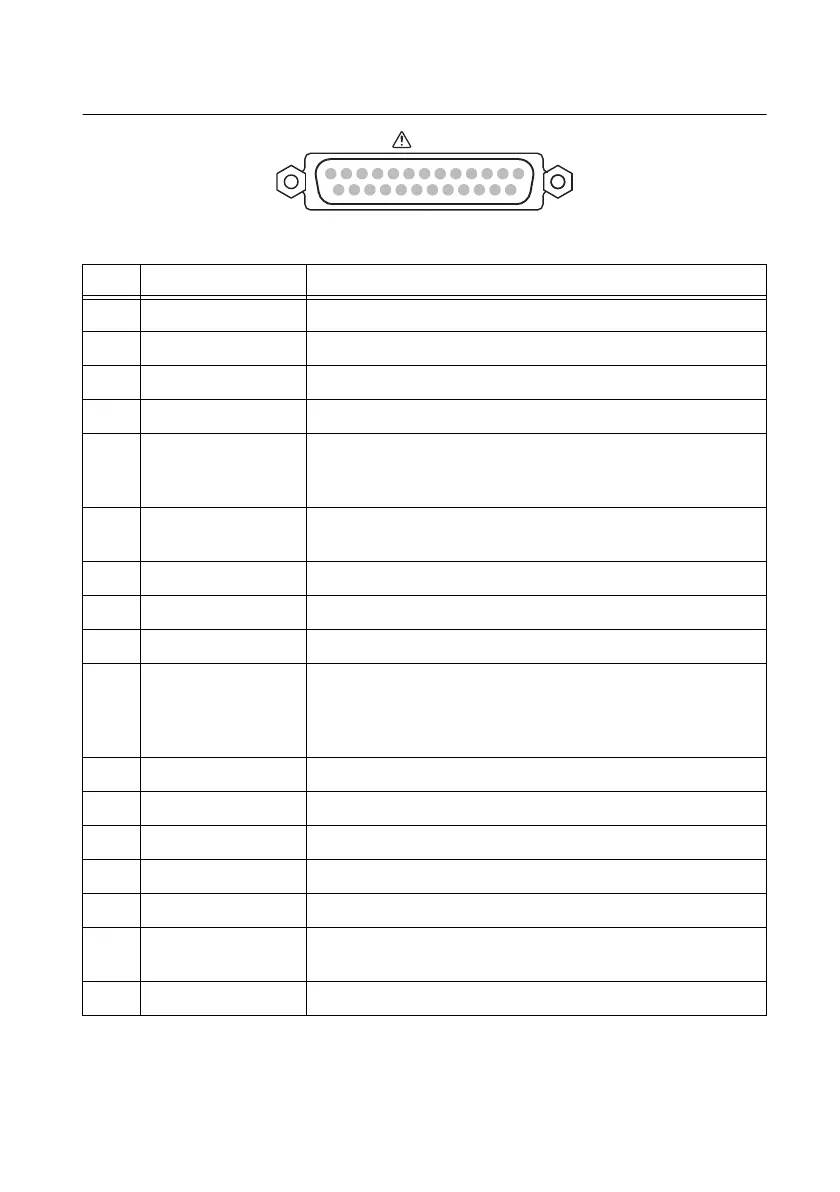
Figure 3-5. J1 Connector Pinout
Table 3-1. J1 Connector Signals
Pin Signal Name Description
1 PRL ON COM Common for pin 16.
2 N.C. Not connected.
3 N.C. Not connected.
4 N.C. Not connected.
5 ALM CLR Alarm clear terminal
Alarms are cleared when a LOW (0 to 5 V) or short-circuit is applied
to this terminal.
6 SHUT DOWN Output shutdown control terminal. The output is turned off when a
LOW (0 to 0.5 V) or short-circuit is applied to this terminal.
7 PRL IN- Negative input terminal for master-slave parallel operation.
8 PRL IN+ Positive input terminal for master-slave parallel operation.
9 PRL COMP IN Correction signal input terminal for master-slave parallel operation.
10 A COM External signal common for pins 5 to 9, 11 to 13, 20 to 22, 24, and 25.
During remote sensing, this is the negative electrode (-S) of sensing
input. When remote sensing is not being performed, this is connected
to the negative output.
11 PRL OUT+ Positive electrode output terminal for master-slave parallel operation.
12 PRL COMP OUT Correction signal output terminal for master-slave parallel operation.
13 I SUM Current signal terminal for master-slave parallel operation.
14 N.C Not connected.
15 N.C. Not connected.
16 PRL ON On during master-slave parallel operation (output through an
open-collector photocoupler).
1
17 N.C. Not connected.
J1
1
2
345
6789
10111213
141516171819202122232425
 Loading...