System Details 17
4.1 Setting the DIP Switches
CAUTION
Do not remove the front cover unless the power to the
boiler is turned off or disconnected. Failure to do so may
result in electric shock.
The boiler has 2 sets of DIP switches on the main circuit board
(PCB) and 2 sets of DIP switches on the front panel. DIP switches
are used to control the functionality of the boiler. Set the DIP
switches appropriately, based on the installation environment.
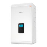
4.1.1 PCB DIP Switches
Dip Switch (Set of 8)
The DIP SW 1 on the circuit board configures boiler type,
capacity, burner type, country, and discharge of condensate
function.
1 2 3 4 5 6 7 8
ON
DIP SW1
Switch Function Setting
1 Boiler Type
SOLO ON
COMBI OFF
2 Reserve
3&4 Capacity
37kW 3-ON, 4-OFF
41kW 3-OFF, 4-ON
5&6 Country
UK 5-OFF, 6-OFF
Not Used 5-ON, 6-OFF
Not Used 5-OFF, 6-ON
Not Used 5-ON, 6-ON
7&8 Boiler Model NCB500 7-ON, 8-OFF
DIP SW2
Switch Function Setting
1 Reserve
3 Reserve
4 Reserve
5&6 Country
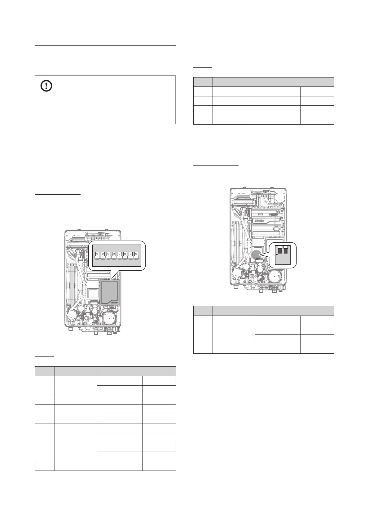
4.1.2 Front Panel DIP Switches
Dip Switch (Set of 2)
The DIP SW on the front panel configures the fuel selection.
1 2
O
N
Switch Function Setting
1 & 2 Fuel selection
LNG(G20) 1-OFF, 2-OFF
Not Used 1-OFF, 2-ON
LPG(G30) 1-ON, 2-OFF
LPG(G31) 1-ON, 2-ON
4. System Details
 Loading...