7-10
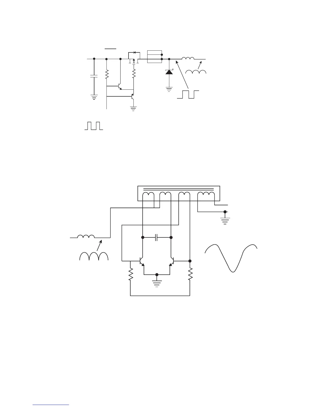
(3) Buck circuit
Used the PMOSFET to control the input power.
LM339
OUTPUT
Q10
R5
Q4
C1
Vin
DC
Q3
Q/S13457DW
6
5
2
1
4
R24
1
D5
1
2
N9
12
100uH
L1
Volt
GND
Vo=DxVin=(Ton/Ts)xVin
N25
Vout (avg) = Vin*D = Vin*(Ton/Ts). Ts: Transformer period Ton: turn on period.
EX: Vout(avg) = 10V, Vin = 15V U, D=(10/15)*100%=66.66%
(4) Royer circuit
100uH
L1
R15
R16
Q5
Q6
C13
0.22u
T1
C13 waveform
23456
110
7
This is a standard Royer structure. It transfer the DC input signal to a AC output single. The resistors R15,
R16 are supply the base current for Q5, Q6. The C13 and transformer decide the oscillation frequency
(working frequency).
EX. If the primary voltage is 15Vrms and the transformer turn ratio is 100.
That secondary voltage is about :15*100=1500Vrms
 Loading...