5-15
1.5.3. Inspection on input signal identification
Purpose of inspection: Confirming that a normal display is obtainable for each signal input.
Unless otherwise specified, the display pattern is as shown in the initial screen,
conforming to 1.2.8 [Inspection mode setting].
--- Inspection of signal input ---
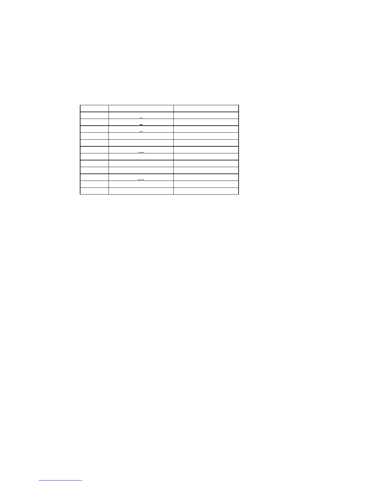
1) According to the table below, make setting of the input connector and the signal, and enter a signal
input.
Item No. Ins
nal No. SYNC
1 1 SEPARATE
2 4 SEPARATE
3 6 SEPARATE
4 8 SEPARATE
5 9 SEPARATE
6 11 SEPARATE
7 12 SEPARATE
8 13 SEPARATE
9 14 SEPARATE
10 17 SEPARATE
11 19 SEPARATE
12 20 SEPARATE
2) When a screen is displayed, visually check whether the display is free from abnormality.
(Freedom from any extreme displacement in position, size, and phase, flickering in the screen, and
extreme color deterioration)
3) Check the OSM menu for the signals that have signal numbers underlined. Display the OSM
information screen (the rightmost tag). Get the [DISPLAY MODE] highlighted with the (3) LEFT or (4)
RIGHT keys. Then, display the [DISPLAY MODE] screen with the (+) PLUS or (-) MINUS key. Confirm
that the displayed definition coincides with the definition of the input signal.
--- Inspection of POWER SAVE ---
4) Remove the output signal of the VG-819 from H.sync and V.sync connector. Confirm that the screen
disappears and the OSM menu of the [NO SIGNAL] is displayed. Wait in this state for about 5 seconds,
and confirm that the LED display is turned into amber and the POWER SAVE mode is assumed.
 Loading...