EasyManuals Logo
Home>NEC>Monitor>MultiSync LCD1550ME

NEC MultiSync LCD1550ME User Manual

NEC MultiSync LCD1550ME
131 pages
To Next Page IconTo Next Page
To Previous Page IconTo Previous Page
Page #81 background imageLoading...
Page #81 background image
6-6
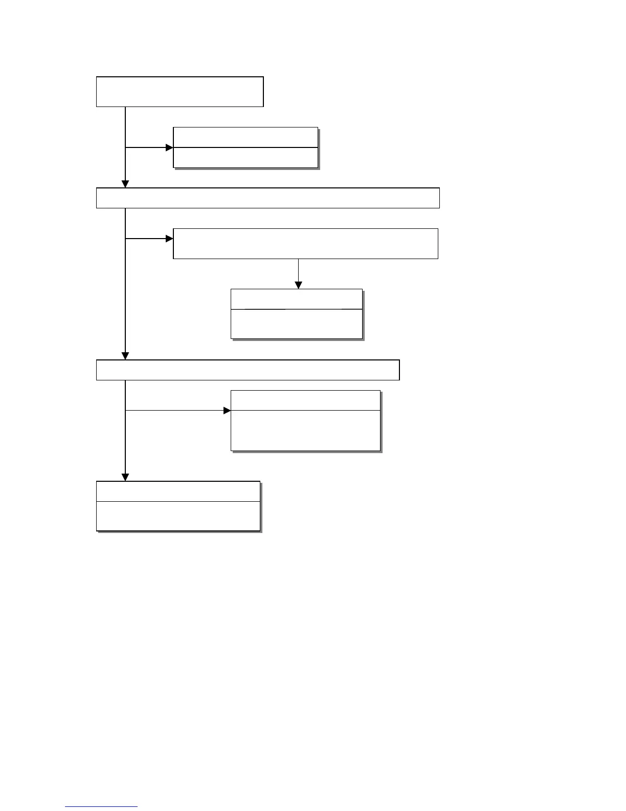
3. Checking the back light unit
Is +15V supplied to P803 pin 3, 4 to
inverter PWB?
OK
NG
Failure point
Inverter cable disconnection.
Check the INV_EN signal of the rectangle input I309 pin 5 at TTL high level
OK
NG
Is a "H" level being output in the TTL level from I302 pin 2
Or, is INV_EN signal of the rectangle being output?
NG
Failure point
Printed wire broke between
I302 pin 2 and I309 pin 5
Check the PWM signal of the input from I302 pin 1 is a BRI signal.
OK
NG
Failure point
1) Printed wire broke between
I302 pin 1 and I309 pin 3.
2
)
I309 failure.
Failure point
1) Inverter cable disconnection.
2) Inverter of LCD module failure.

Table of Contents

Questions and Answers:

Question and Answer IconNeed help?

Do you have a question about the NEC MultiSync LCD1550ME and is the answer not in the manual?

NEC MultiSync LCD1550ME Specifications

General IconGeneral
BrandNEC
ModelMultiSync LCD1550ME
CategoryMonitor
LanguageEnglish

Related product manuals