English
English−25
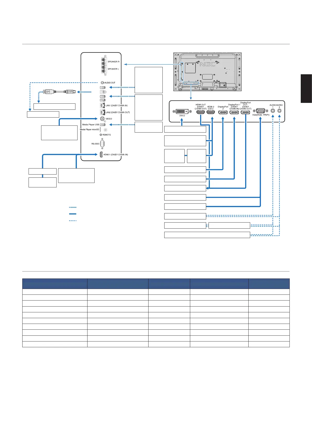
Wiring Diagram
USB1 (SENSOR)
USB2
USB CM1 (2A)
USB CM2
AUDIO
1
Dotted lines = other signal
Solid lines = video signal
Dashed lines = audio signal
VCR Player or
DVD Player (Video)
Stereo Amplifier
USB port
(Type-A)
USB devices
such as a
USB camera,
USB storage
device or USB
color sensor
Devices that
require power
supply:
Ex: Multi
Presenter stick
USB storage
device
USB port
(Type-B)
USB cable
Computer (USB)*
1
AV Amplifier
Blu-ray or DVD
Player (HDMI)
HDMI video player or
Computer (HDMI)
Computer (Digital)
HDMI video player or
Computer (HDMI)
Blu-ray or
DVD Player
(HDMI)
AV
Amplifier
Computer (DisplayPort)
Computer (DisplayPort)
Second monitor*
Computer (Analog)
Computer
DVD Player (component)
DVD Player Stereo Amplifier
VCR player or DVD player
*: Multiple monitors that are daisy-chained have a limit to the number of connectible monitors. See page 71.
*
1
: The device connected to USB2 can control the device connected to USB1 (SENSOR). See the “Connecting a USB Device” on page 31.
Connections
Connecting terminal
Setting in
TERMINAL SETTINGS
Input signal name Connecting audio terminal
Input button in remote
control
DVI (DVI-D) DVI MODE: DVI-PC/DVI-HD DVI IN1/IN2 DVI
HDMI1 (DAISY CHAIN IN) VIDEO LEVEL: RAW/EXPAND*
2
HDMI1 HDMI1 HDMI1
HDMI2 (CEC) VIDEO LEVEL: RAW/EXPAND*
2
HDMI2 HDMI2 HDMI2
DisplayPort 1 (DAISY CHAIN IN) VIDEO LEVEL: RAW/EXPAND*
2
DisplayPort 1 DisplayPort 1 DisplayPort 1
DisplayPort 2 VIDEO LEVEL: RAW/EXPAND*
2
DisplayPort 2 DisplayPort 2 DisplayPort 2
VGA (RGB, YPbPr) VGA MODE: RGB/YPbPr VGA: RGB/YPbPr IN1/IN2 VGA (RGB/YPbPr)
VIDEO — VIDEO IN1/IN2 VIDEO
Option Board Slot (SLOT2) VIDEO LEVEL: RAW/EXPAND*
2
OPTION OPTION (ANALOG/DIGITAL)*
2
OPTION
Media Player USB/microSD — MP Media Player USB/microSD MEDIA PLAYER
Raspberry Pi Compute Module slot VIDEO LEVEL: RAW/EXPAND*
2
COMPUTE MODULE COMPUTE MODULE COMPUTE MODULE
*
2
: Please set appropriate setting for input signal.
 Loading...