PAGE 40 / 80 NXAMPMK2 USER MANUAL
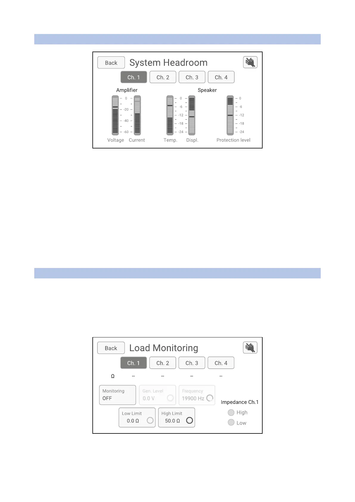
SYSTEM HEADROOM
The System Headroom menu displays for each channel (selected by the top buttons Ch.1 to Ch.4) the
headroom available from both the amplifier channel and the speakers connected to it.
On the amplifier headroom monitoring part, two vu-meters with a 60 dB scale are displaying the Output
Voltage and the Output Current, both referring to 0 dB being the maximum voltage of the maximum current
the amplifier can output. Please note that these maximum values are dependent on the NXAMPmk2 model.
On the speaker headroom monitoring part, three view meters with a 24 dB scale are displaying the
temperature of the voice coils of the connected speakers, the displacement of the membranes, both referring
to 0 dB being the maximum temperature and the maximum displacement the speakers can safely reach.
The last view meter is showing how much the NXAMPmk2 is reducing the output level to protect the
speakers. This is a global meter displaying the maximum of all protections applied to the speaker, being a
frequency selective displacement protection using a VCEQ (Voltage Controlled EQ), a wideband thermal
protection for LF or HF driver for example, a peak limiter protection etc.
LOAD MONITORING
The NXAMPmk2 Load Monitoring is an impedance monitoring function, measuring in real-time the
impedance on the amplifier output channel. This allows to report (through its GPIO port or network) whether
the speakers are correctly connected to the amplifier and ready to use. This function can be enabled and
configured on every channel.
This is particularly useful for safety installations where the status of connected speakers should always be
known, and any fault in the audio chain should be reported.
This menu allows setting up all the NXAMPmk2 Load Monitoring parameters per channel. Basically, this
monitoring function measures the impedance on the amplifier channel at one frequency point and can report
 Loading...


