21 – English
English
AUTOMATION TESTING AND COMMISSIONING
CAUTION! – All operations described in chap-
WHUVPD\FRQVWLWXWHDKD]DUG7KHUHIRUH
they must be performed exclusively by skilled
DQGTXDOLƄHGSHUVRQQHOLQREVHUYDQFHRIWKHVH
instructions and current safety standards appli-
cable in the place of use.
––– STEP 8 –––
SETTING THE ELECTRICAL LINE
FOR PERMANENT POWER SUPPLY
After programming, before testing and commissioning the automation,
it must be permanently connected to the mains by means of a special
power line equipped with a disconnect device.
8.1 - CONNECTING THE AUTOMATION PERMANENTLY
TO THE POWER MAINS
CAUTION! – ,QFRUUHFWFRQQHFWLRQVFDQFDXVHIDXOWVRUKD]DUGRXV
VLWXDWLRQVWKHUHIRUHVWULFWO\REVHUYHDOOFRQQHFWLRQVVSHFLƄHGLQ
this paragraph.
8.1.1 - Replacement of the power cable
01. Remove the power supply unit
To perform this operation, read the instructions in paragraph A.2
(chapter “Further details”), but only disconnecting the wires phase
and neutral (there is no need to disconnect the earth wire or connec-
tor with the 5-cable plate).
02. In the area housing the power supply unit, remove the screw securing
the eyelet of the earth wire (ƄJ).
03. Remove the control unit
To perform this operation, read the instructions in paragraph A.1
(chapter “Further details”).
Replace the cable
Loosen the cable clamp screws; withdraw the power cable (supplied
@RRS@MC@QC@MCHMRDQSSGDMDVB@AKDENQB@AKDRODBHjB@SHNMRQDEDQ
to paragraph 3.3.4).
05. Strip the cable to approx. 80 mm, and the phase and neutral wires,
after which insert the sheath taken from the previous power cable.
06. Connect the phase and neutral wires to the power supply unit termi-
M@KAN@QCNARDQUHMFSGDRODBHjB@SHNMRNMSGDK@ADK
07. On the earth wire, insert a crimp terminal without insulation, using a 6
mm eyelet.
08. In the area housing the power supply unit, use a screw to secure the
SVNDXDKDSRENQSGDD@QSGVHQDRjFl"@TSHNMŬ#HQDBSSGDBQHLO
terminal towards the outlet of the power cable).
09.2KNVKXOTKKSGDONVDQB@AKDCNVMV@QCRTMSHK@RTEjBHDMSB@AKDKDMFSG
is left to rotate and close the power supply unit.
10.3GDMjQLKXONRHSHNMSGDRD@KHMHSRRD@S@MCBKNRDSGDONVDQRTOOKX
unit cover with all screws (caution! - A missing seal or screw may
cause problems with internal electronics).
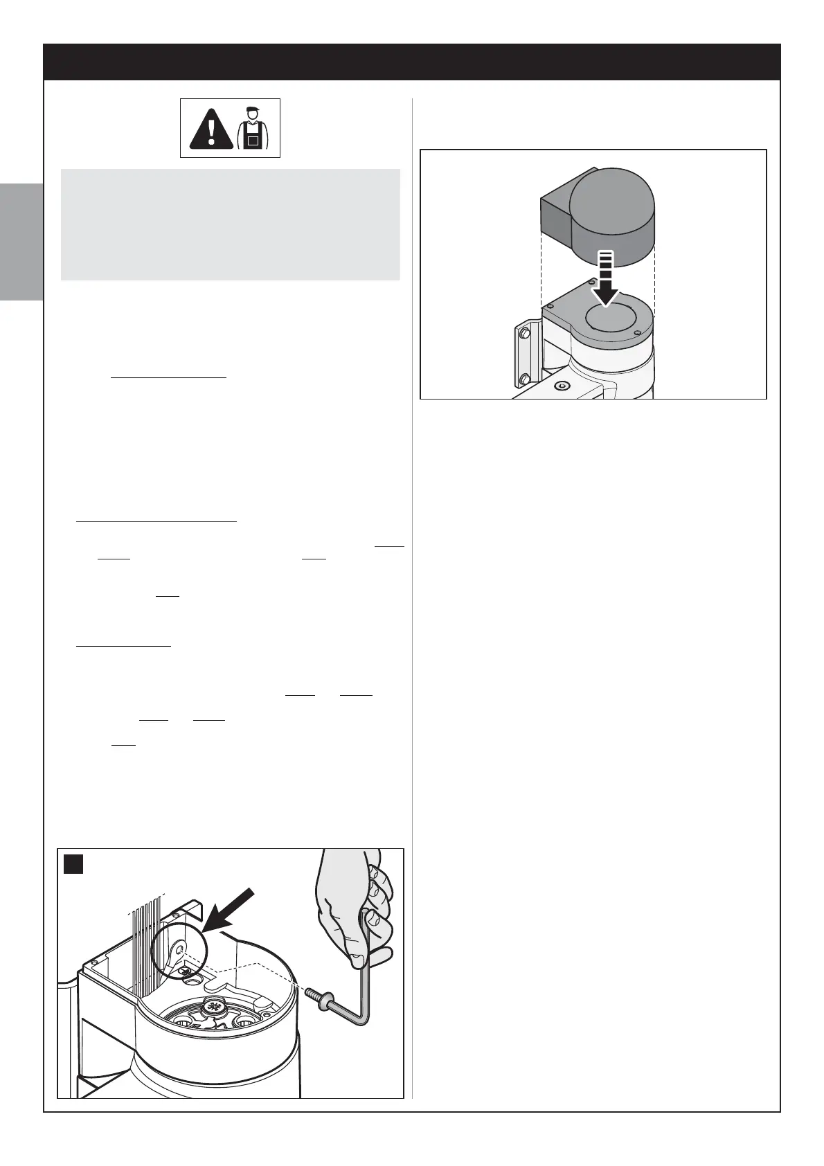
11. Insert the protective cover on top of the motor.
12. Lastly, tighten down the screws of the cable clamp, insert the control
TMHSHMHSRRD@SQDjSSGDB@AKDCTBSHMFRTOONQS@MCQDjSSGDKNVDQBNUDQ
of the gearmotor.
8.1.2 - Installing the safety devices on the electrical line
The automation power line must be equipped with a device for protection
against short circuits and a device for disconnection of the automation
from the power mains (neither devices are supplied with the kit).
3GDCHRBNMMDBSCDUHBDLTRSG@UDBNMS@BSRVHSG@RTEjBHDMSF@OSNDMRTQD
complete disconnection, in compliance with the overvoltage category III,
according to the installation instructions.
If necessary, this device guarantees quick and safe disconnection from
the mains power and therefore must be positioned in sight of the automa-
tion. If located in a concealed position, it must be equipped with a system
that prevents inadvertent or unauthorised reconnection of power, to avoid
ONSDMSH@KG@Y@QCR
––– STEP 9 –––
AUTOMATION TESTING
AND COMMISSIONING
Testing and commissioning of the system are the most important phases
in automation set-up, as they will guarantee maximum system safety.
The testing procedure described below may also be used to periodically
check the devices making up the automation.
Testing and commissioning of the entire system must be per-
IRUPHGE\VNLOOHGDQGTXDOLƄHGSHUVRQQHOZKRDUHUHVSRQVLEOHIRU
the tests required to verify the solutions adopted according to the
risks present, and for ensuring observance of all legal provisions,
standards and regulations and in particular all requirements of the
VWDQGDUG(1ZKLFKHVWDEOLVKHVWKHWHVWPHWKRGVIRUFKHFN-
ing automations for gates.
9.1 - TESTING
01. Ensure that all instructions and warnings in STEP 1 have been strictly
observed.
02. Using the radio transmitter, test a gate closing and opening cycle
@MCDMRTQDSG@SSGDKD@ELNUDLDMSBNQQDRONMCRSNRODBHjB@SHNMR
number of tests should be performed to ensure that the gate moves
smoothly and that there are no assembly defects, incorrect settings,
or any points of friction.
03. Ensure correct operation of all safety devices in the system (photo-
cells, sensitive edges, etc.), by activating them one at a time during an
opening and/or closing manoeuvre. In particular, each time a device is
activated, check on the control unit that the Led “BUS” emits a longer
k@RGSGHRBNMjQLRSG@SSGDBNMSQNKTMHSG@RQDBNFMHRDCSGDDUDMS
To test photocells and in particular that there is no interference with
other devices, pass a cylinder (diameter 5 cm, length 30 cm) through
the optic axis (ƄJ/@RRSGDBXKHMCDQjQRSBKNRDSNSGD37OGNSN-
cell, then close to the RX and lastly at the centre between the two.
Ensure that in all cases the device engages, changing from the active
status to alarm status and vice versa, and that the envisaged action is
30

 Loading...