English –
English
9 - Product durability. The lifetime is the average economic duration of
SGDOQNCTBS3GDU@KTDNEKHEDSHLDHRRSQNMFKXHMkTDMBDCAXSGDHMSDM-
sity of the manoeuvres, i.e. the sum of all factors that contribute to
product wear; these values are shown in Table 1 and we therefore
recommend making an estimate of the automation lifetime after com-
missioning, using the following calculation:
01. In T
able 1, locate the values “Leaf length” and “Leaf weight” of
your gate and note the corresponding “Severity index”, taking car
e to
check the length of the arm on which the gearmotor is installed. In the
RODBHjBBNMSDWSHESGDQD@QDNSGDQE@BSNQRSG@SHMkTDMBDRSQDRRNESGD
manoeuvre, locate the relative values in T
able 1 and add them to the
sum obtained befor
ehand.
Example
: • “Leaf length” = 1,5 m; “leaf weight” = 92 kg; “arm length”
= standard; therefore, severity index = 55%.
3UHVHQFHRIIDFWRUVLQƅXHQFLQJVWUHVVRQWKHPDQRHXYUHVsqDPEL-
HQWWHPSHUDWXUHr 1RqVROLGOHDIr <HVqDUPOHQJWKr VWDQGDUG
therefore, severity index = 15%q,QVWDOODWLRQLQZLQG\]RQHr <HV
“arm length” = standard; therefore, severity index = 15%. • TOTAL
INDEX: 55% + 15% + 15% = 85%.
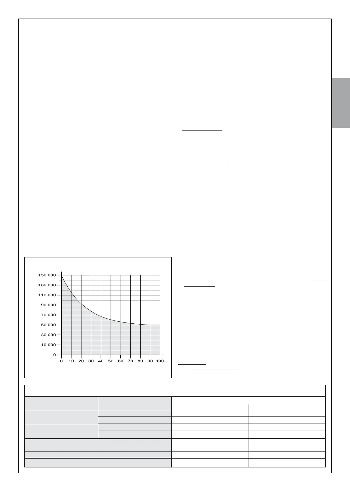
02. In Graph 2, note the total value of severity obtained (in the exam-
ple = 85%) and trace a vertical line fr
om this point, until it intersects
the curve in the graph. Then, fr
om the point of intersection, trace
@GNQHYNMS@KKHMDSGQNTFGSNSGDUDQSHB@K@WHRNESGDFQ@OG3GDU@KTD
obtained (number of manoeuvre cycles) represents the estimated
durability of the product.
Example: total severity index = 85%. In Graph 1, this corr
esponds to
appr
oximately 51,000 manoeuvre cycles (= product durability).
3GDKHEDSHLDU@KTDRRODBHjDCHMSGDFQ@OG@QDNMKXNAS@HM@AKDHESGD
maintenance schedule is strictly observed (see paragraph 10.1). The
estimation of lifetime is made on the basis of design calculations and
the results of tests performed on prototypes. As it is only an estima-
tion, it does not represent any form of guarantee on the effective life-
time of the product.
3.3 - PRELIMINARY CHECKS FOR INSTALLATION
3.3.1 - Ensure all equipment and materials for work are
available
Before starting work, ensure that you have all equipment and materials
required to complete the work. Ensure that all items are in good condition
and comply with local safety standards.
3.3.2 - Establish the position of devices in the system
To establish the installation position of each device envisaged in the sys-
tem, refer to ƄJ This illustrates a system set up using the components
supplied in the kit as well as other optional devices and accessories. The
jFTQDRGNVR@MHCD@KK@XNTSNESGDCDUHBDR3GDCDUHBDRTRDC@QD
a - Electromechanical gearmotor with control unit ALTO100C
b - Electromechanical gearmotor without control unit ALTO100M
c - Pair of photocells PH200 (wall-mounted)
d - Flashing light FL200
e - Opening travel limit stops WKHVHDUHQRWSDUWRIWKH1LFH+RPHSURG-
XFWUDQJHWKH\PD\DOVRFRQVWLWXWHqQDWXUDOrREVWDFOHVVXFKDVDZDOO
HGJHRIDƅRZHUEHGHWF
f - Closing travel limit stop WKLVLVQRWSDUWRIWKH1LFH+RPHSURGXFW
UDQJH
When selecting the position of each device, take special care to observe
the following:
• Gearmotors – the gearmotor with control unit must be positioned on
SGDKD@EBKNRDRSSNSGDYNMDVGDQDSGDONVDQRTOOKXHRKNB@SDC
• PH200 photocells – the two photocells (TX and RX) must be posi-
tioned: a) at a height of 40-60 cm from the ground; b
) to the sides of the
YNMD
SNADOQNSDBSDCc
) outside the gate, i.e. on the side of the public
r
oad; d) trim with the gate (max. 15 cm from the latter); e) the TX photo-
cell (transmitting) must be directed at the RX photocell (r
eceiving), with a
maximum tolerance of 5°.
• )/
ƅDVKLQJOLJKW – this must be positioned in the vicinity of the
gate; it must also be easily visible fr
om any point of access to the gate.
NotelSGDCDUHBDB@MADjWDCSN@GNQHYNMS@KNQUDQSHB@KRTQE@BD
• 2WKHU
Ƅ[HGW\SHFRQWUROGHYLFHV
– these must be positioned in view
of the automation, far from all moving parts at a minimum height of 1.5
m fr
om the gr
ound; they must also not be accessible by unauthorised
persons.
3.3.3 - Setting the route of the connection cables
To establish the route of each connection cable and thus dig the race-
ways for the cable ducting, the following constraints must be taken into
account:
a
) points envisaged for device installation (r
ead paragraph 3.3.2);
b
) the envisaged connection between all devices and terminals
involved (see ƄJ);
c
) “ECSBus” technology. This technology enables the connection and
communication between several devices (including the control unit by
means of the BUS terminal) with a single cable containing 2 electrical
wires (carrying the electric power and data communication signals).
This cable can only be used to connect Nice Home devices compatible
with the ECSBus pr
otocol: for example the photocells, safety devices,
control buttons, indicator lights etc. (for information on compatible
devices, r
efer to the Nice Home catalogue or visit the website www.
niceforyou.com). “ECSBus” technology of
fers the possibility of using
dif
ferent layouts for device connections. Some examples ar
e shown in
ƄJ
.
After considering points a, b, c, observe ƄJ and on a piece of paper
CQ@V@RHLHK@QK@XNTS@C@OSHMFHSSNSGDRODBHjBMDDCRNEXNTQRXRSDL3GHR
layout will serve as a guideline to dig the raceways for the cable ducting
and to make a complete list of the cables required.
3.3.4 - Selecting and sizing all connection cables
To select the type of cables and cut these to an adequate length, consult
Table 2; then, with the aid of the previously drawn layout (ref. paragraph
3.3.3), make on-site measurements to establish the length of each cable.
Caution!-NB@AKDLTRSDWBDDCSGDRODBHjBL@WHLTLKDMFSGRS@SDCHM
Table 2.
Power cable – The power cable on the ALTO100C gearmotor serves to
make provisional connections to the mains (for example, to perform pro-
gramming and the operation tests). Then, to test and start-up the auto-
GRAPH 2 (see paragraph 3.2 - 9)
manoeuvre cycles
severity index (%)
TABLE 1 - Severity index (see paragraph 3.2-9)
Severity index
STANDARD arm length SHORT arm length
< 1,2 m
1,2 - 1,6 m
1a - Leaf length 1b - Leaf weight
$PELHQWWHPSHUDWXUHRYHU&RUORZHUWKDQ&RUKXPL-
dity greater than 80%
3 - Solid leaf
,QVWDOODWLRQLQZLQG\]RQH
> 100 kg
< 100 kg
> 80 kg
< 80 kg
55%
30%
55%
65%
50%
65%
50%
15%
15%
15%
15%
10%
10%
 Loading...