25 – English
English
degrees of latitude of this location (J(D GHJUHH 1.
02. On the graphs (North or South) supplied in the SOLEKIT instruction
manual, locate the curve for the location’s latitude (e.g: 45°N).
03. Choose the period of the year on which to base the calculation, or
select the lowest point of the curve to calculate the worst period
of the year; then read the corresponding value Am (e.g. December,
January: Am= 200).
Calculate the value of energy available Ed (produced by the panel)
multiplying Ea x Am = Ed H[DPSOH(D $P LH(G
.
• Calculating the energy consumed
To calculate the energy consumed by the automation, proceed as follows:
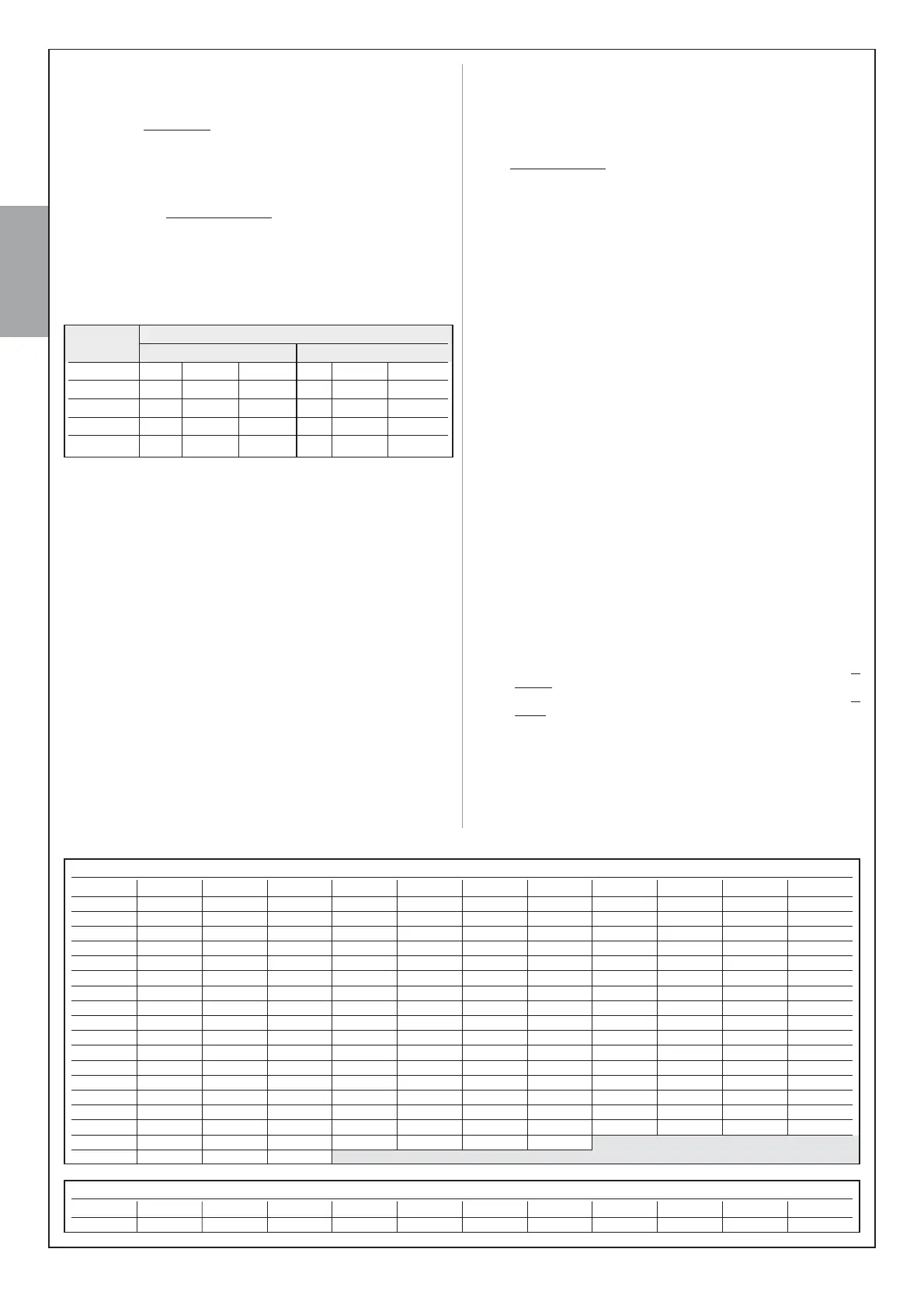
05. On the table below, select the box corresponding to the intersection
between the line with the weight and the column with the opening
angle of the leaf. The box contains the value of the severity index
(K) for each manoeuvre (e.g. gearmotor with standard arm on leaf of
NJDQGRSHQLQJ.
Opening angle
with standard arm with short arm
Leaf weight ¦ ¦ ¦ ¦ ¦ ¦
< 80 kg 30 44 60 60 84 112
80-120 kg 42 58 90 90 128 200
120-150 kg 55 84 144 144 220 288
150-180 kg 86 126 220
motor
06. On the WDEOH select the box corresponding to the intersection
between the line with the Ed value and the column with the K value.
The box contains the maximum possible number of cycles per day
HJ(G . F\FOHVSHUGD\ .
If the number obtained is too low for the envisaged use or is located in the
“area not recommended for use”, the use of 2 or more photovoltaic pan-
els may be considered, or the use of a photovoltaic panel with a higher
power. Contact the Nice technical assistance service for further informa-
tion.
The method described enables the calculation of the maximum possible
number of cycles per day that can be completed by the automation while
running on solar power. The calculated value is considered an average
value and the same for all days of the week. Considering the presence
of the battery, which acts as an energy “storage depot”, and the fact that
the battery enables automation autonomy also for long periods of bad
weather (when the photovoltaic panel produces very little energy) it may
be possible to exceed the calculated maximum possible number of cycles
per day, provided that the average of 10-15 days remains within the envis-
aged limits.
Table 5RODBHjDRSGDL@WHLTLONRRHAKDMTLADQNEBXBKDR@BBNQCHMF
to the manoeuvre’s severity index (K), using exclusively the energy
stored by the battery. It is considered that initially the battery is com-
pletely charged (e.g. after a prolonged period of good weather or recharg-
ing via the optional PCB power supply unit) and that the manoeuvres are
performed within a period of 30 days.
When the battery runs out of the stored energy, the led starts to indicate
SGDA@SSDQXKNVRHFM@KAXk@RGHMFAQHDkXDUDQXRDBNMCR@BBNLO@MHDC
by a “beep”.
If the “ALTO” is used on a single leaf gate (with only one gearmotor),
the maximum possible number of cycles corresponds to the value in the
tables, multiplied by 1.5. For example, if the calculated number of cycles
is 30 and the gate has one leaf only, the number of cycles will be: 30 x
1,5 = 45.
A.6 - “Stand-by” function when the device PR200
and/or SOLEKIT is installed RSWLRQDOGHYLFHV
When the automation is powered by the backup battery PR200 or the
photovoltaic system SOLEKIT, the “standby” function is activated auto-
matically 60 seconds after completion of an automatic manoeuvre cycle.
This turns off the “BUS” output and all connected devices, the outputs
“Flash”, “Els” and all leds, with the exception of the BUS led which
k@RGDRLNQDRKNVKXk@RGDUDQXRDBNMCR ESDQSGHR@RRNNM@RSGD
user sends a command, the control unit restores power and starts the
manoeuvre WKLVPD\VWDUWZLWKDVKRUWGHOD\.
A.7 - Using the “BUS” input/output
Only devices compatible with ECSBus technology must be connected to
the terminal “BUS” (this is explained in detail in paragraph 3.3.3). Impor-
tant – Following testing of the automation, each time new devices
are connected to (or removed from) the “BUS” terminal, the learn-
ing procedure must be performed as described in paragraph A.10.
A.8 - Using the “STOP” input
STOP is the input that causes immediate shutdown of the manoeuvre
(with brief inversion). This input can be connected to devices with contact
types Normally Open, Normally Closed (NC) or devices with a constant
QDRHRS@MBDNE*ƄRTBG@RRDMRHSHUDDCFDR
When set accordingly, more than one device can be connected to the
STOP input, also different from one another. For this function, refer to
Table 6 and the following notes to the table.
Note 1.7KHFRPELQDWLRQ12DQG1&LVSRVVLEOHE\FRQQHFWLQJWKH
FRQWDFWVLQSDUDOOHOWDNLQJFDUHWRFRQQHFWDNŭUHVLVWDQFHWR
WKH1&FRQWDFWWKLVHQDEOLQJWKHFRPELQDWLRQRIGHYLFHV12
1&DQG.ŭ
Note 2.$Q\QXPEHURI12GHYLFHVFDQEHFRQQHFWHGWRHDFKRWKHUin
parallel.
Note 3.$Q\QXPEHURI1&GHYLFHVFDQEHFRQQHFWHGWRHDFKRWKHUin
series.
Note 4.7ZRGHYLFHVZLWKDNŭFRQVWDQWUHVLVWDQFHFDQEHFRQQHFWHG
LQSDUDOOHO+RZHYHULIWKHUHDUHPRUHWKDQWZRRIWKHVHGHYLFHV
WKH\PXVWEHFRQQHFWHGqLQFDVFDGHrSODFLQJRQO\RQHWHUPLQDW-
LQJUHVLVWDQFHRINŭ
Warning! – If devices with safety functions are connected to the “STOP”
input, only devices with a constant 8,2k1 resistance output can guaran-
tee fault safety category 3.
7$%/(0D[LPXPQXPEHURIF\FOHVSHUGD\VHHSDUDJUDSK$
(G .ƀ .ƀ . . . . . . . . .
9500 183 122 92 73 61 52 46 41 37 33 31
9000 173 115 87 69 58 49 43 38 35 31 29
8500 163 109 82 65 54 47 41 36 33 30 27
8000 153 102 77 61 51 44 38 34 31 28 2
7500 143 95 72 57 48 41 36 32 29 26 24
7000 133 89 67 53 44 38 33 30 27 24 22
6500 123 82 62 49 41 35 31 27 25 22 21
6000 113 75 57 45 38 32 28 25 23 21 19
5500 103 69 52 41 34 29 26 23 21 19 17
5000 93 62 47 37 31 27 23 21 19 17 16
83 55 42 33 28 24 21 18 17 15 14
73 49 37 29 24 21 18 16 15 13 12
3500 63 42 32 25 21 18 16 14 13 11 11
3000 53 35 27 21 18 15 13 12 11 10 9
2500 43 29 22 17 14 12 11 10 9 8 7
2000 33 22 17 13 11 9 8 7 7 6 6
1500 23 15 12 9 8 7 6
1000 13 9 7
Area of use not recommended
TABLE 5 - Maximum number of cycles using exclusively battery power VHHSDUDJUDSK$
.ƀ .ƀ . . . . . . . . .
1082 721 541 433 361 309 271 240 216 197 180

 Loading...