2 – English
EN
CONTROL and CONNECTION ELEMENTS
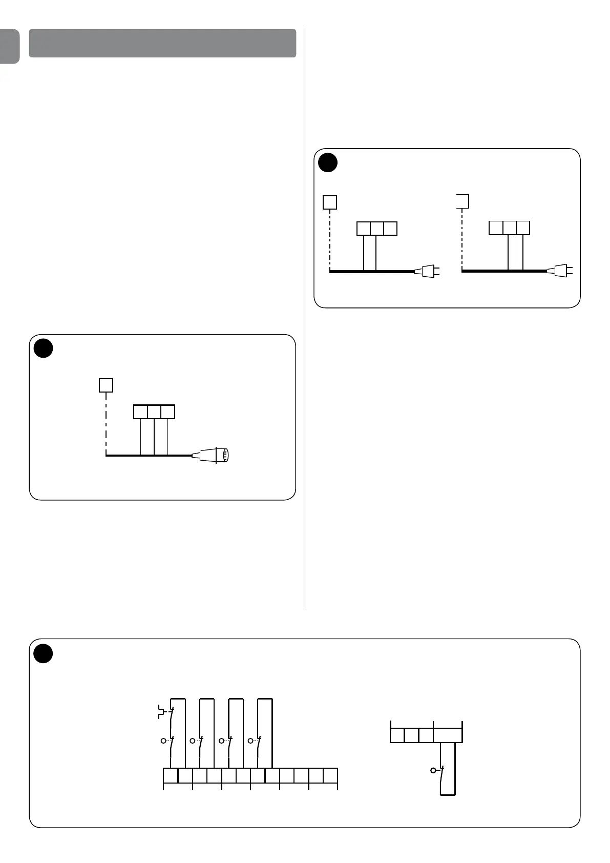
Connection of the three-phase power supply cable
(g.1)
A16AEECplugisconnectedtoterminalsL1,L2,L3andthePE
terminal.
TheconnectiontotheUST1Kstationcanalsobecarriedoutwith
the optional three-phase main switch.
InthiscaseitispossibletoremovetheEECplugduringassembly.
Control elements
ItispossibletocontroldoorOPENINGandCLOSINGwiththebut-
tonsbuiltintothecoverinautomaticand/ordeadmanmode.
Ifsetinautomaticmode,thedoorcanbestoppedatanytimewith
theSTOPbutton.
Itispossibletoconnectothercontrolelementsforcontrolfromthe
outside,atriplebuttonforexample.
Aswitchwithacablecomingdownfromtheceiling,installedinside
oroutside,controlsthedoorintheOPENSTOPCLOSEfunction.
Iftheoptionalradioreceiverisconnected,itisalwayspossibleto
stop the door with the manual radio transmitter.
Direction of rotation control
Ifthedoorisinthelowernalposition,nowitisnecessarytoopen
itbyabout50cmwiththehandletopreventthetrackropesfrom
comingoutoftheirhousing(sectionaldoors)orexcessivewindingof
the rolling shutter in the case of rotation is reversed.
Check the direction of rotation in deadman mode with the UP and
DOWNbuttons.ItisnecessarytodisconnecttheEECplugandre-
versethe U andV connections (phasereversal)ifthe directionof
rotation does not correspond to the direction of the arrown on the
pressedbutton.
Now power up (connect the EEC plug).
Limit switch setting (g.3)
ThetwoOPENINGandCLOSINGlimitswitchesmustbeconnected
likezeropotentialcontactstoterminalsJ27andJ26oftheterminal
blockX7intheUST1controlunit.Thesafetycircuitwiththeinte-
gratedlimitswitchesistobeconnectedtoterminalJ29ofterminal
blockX7.
Itisalsopossibletoconnectasecond,additionallimitswitchforthe
opening function (J33/X6) and then choose between two different
OPENINGpositions(summerwinterswitching)withapositionswitch
installedonthehousingcover(optional)oftheUST1Kstation,.
The procedure for setting the limit switches is described be-
low.
1
PE
L1
X1
L2
L3
Power supply cable
EEC 16° plug
2
PE
X1
L1
Power supply
cable SCHUKO plug
L2
PE
X1
L3
Power supply cable
SCHUKO plug
L2
UST1K-1.1kW
UST1K- starting
from 2.2kW
N
L1
N
L1
3
+ B A
J35 J34
12V DC RS485
X7
Emergency
handle
Thermal
switch
Pre-limit switch
-
Limit switch DOWN
Limit switch DOWN
J29 J28 J27 J26
Thermal
switch
Preliminary
limit switch
closed
STOP
totally
opened
+S
X6
SKS
o.DW
J32
half OPEN
J33
Half-height
limit switch
-
1/2
STOP
STOP
Single phase power supply cable connection (g.2 –
also see page 6)
ASchukoplugisconnectedtoterminalsL1(phase)andL2(N)and
to terminal PE in the 1.1 kW UST1K – station. The plug is connected
toL2(phase),L3(N)andPEontheversionswithhigherpowers(2.2
kWand5.5kW).
ConnectiontotheUST1K1.1kWstationcanalsobemadewithan
optional single-phase main switch.
InthiscaseitispossibletoremovetheSchukoplugduringassembly.
 Loading...