English – 16
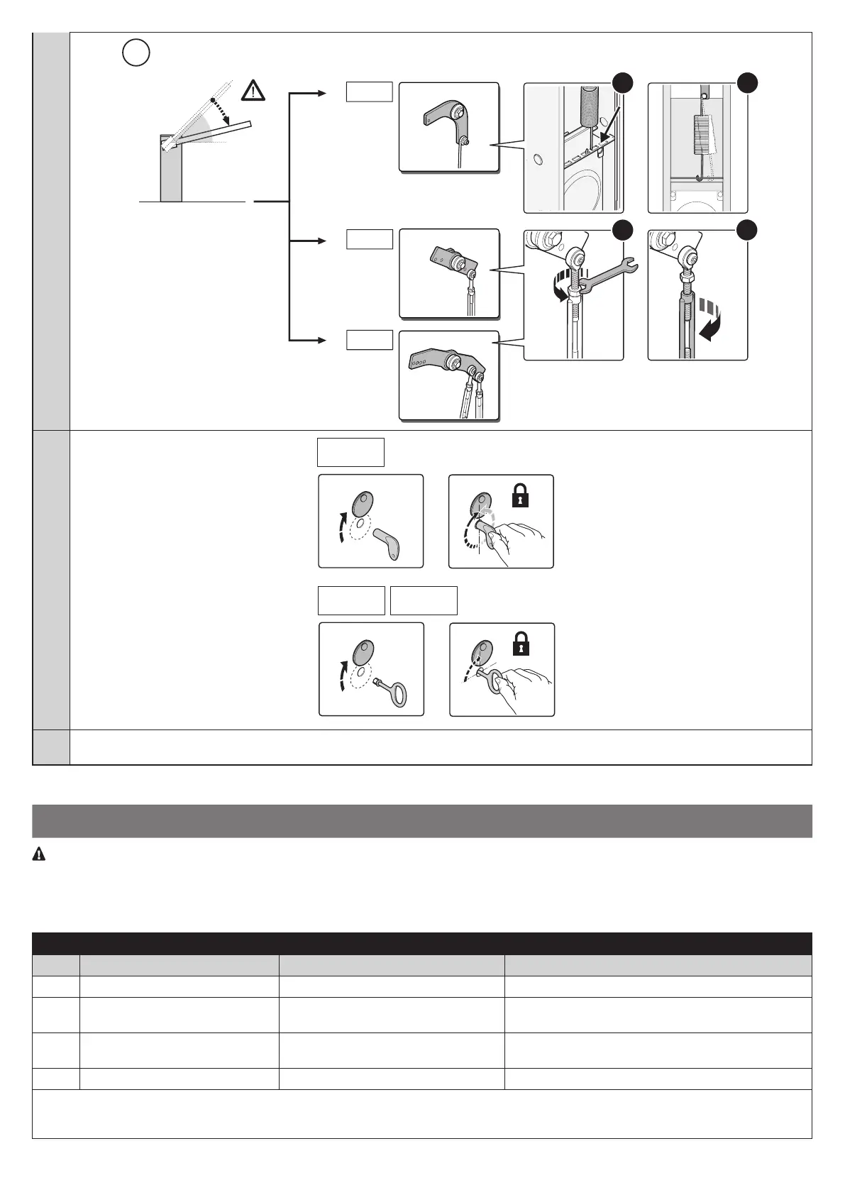
45°
WIDE S
a
b
WIDE
M
a
b
WIDE L
14. Lock the gearmotor
(based on the purchased model)
WIDE
S
WIDE
S
WIDE M WIDE L
WIDE
S
WIDE
WIDE
15. If any other devices (accessories) are intended for the system, they must be installed at this point: refer to the respective instruction
manuals and Section 8 (Further details) in this manual
4
ELECTRICAL CONNECTIONS
CAUTION! - All electrical connections must be made with the system powered off Incorrect connections can result in damage
and injury.
Fig. 4 shows the hookup of a typical installation; g. 5 shows the connections to be made on the control unit.
4.1 - Types of electrical cables: Fig. 4
Table 3 - Types of electrical cable (see g. 4)
Connection Type of cable Maximum length
A POWER 3 x 1.5 mm
2
30 m *
B
C
FLASHER WITH AERIAL 1 cable: 2 x 1.5 mm
2
1 shielded RG58 cable
10 m
10 m (< 5 m recommended)
D PHOTOCELLS 1 cable: 2 x 0.25 mm
2
(TX)
1 cable: 4 x 0.25 mm
2
(RX)
30 m
30 m
E - F KEY SWITCH 2 cables: 2 x 0.5 mm
2
** 20 m
* A power supply cable longer than 30 m may be used provided it has a larger gauge, e.g. 3x2.5mm
2
, and that a safety grounding system is
provided near the automation unit.
** The two 2 x 0.5 mm
2
cables can be replaced by a single 4 x 0.5 mm
2
cable.
 Loading...