English – 18
TX
NC NO CC NO NC
1 2
RX
FLASH
T1
T2
21 543
TX
1 2
RX
21 543
LED FCC
LED OK
LED
MOTOR
FLASH
PHOTO PHOTO PHOTO2 PHOTO2
+
0 V
+ 24 V
+ 24 V
PROGRAM SWITCH
LIMIT
SWITCH
TRIMMER TP FL FRI
FUSE
24 V
CLOSE
OPEN
P. P.
PHOTO2
PHOTO
ALT
LED FCA
1
2
3
4
5
6 78
9
10
15
14
13
12
111098765
4
3
24 V
PS324
SM
5
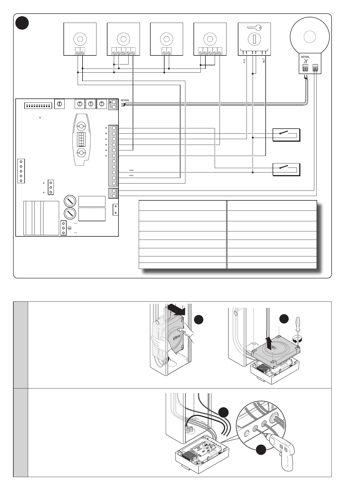
AERIAL = AERIAL LED PHOTO =
PHOTOCELL
LEDS
PROGRAM
SWITCH
=
MICRO
SWITCHES
LED FCC =
CLOSING LIMIT
SWITCH LED
TRIMMER =
ADJUSTMENT
TRIMMER
LED FCA =
OPENING LIMIT
SWITCH LED
LED OK = OK LED LIMIT SWITCH = LIMIT SWITCH
LED OPEN = OPEN LED FLASH = FLASHING LIGHT
LED CLOSED = CLOSED LED FUSE = FUSE
LED P.P. = STEP-BY-STEP LED MOTOR = MOTOR
LED PHOTO2 = PHOTOCELL LEDS
To make the electrical hookup, proceed as described below with reference to Fig. 5:
01. a - unhook the control unit box from its
position
b - open the box
a
b
02. c - drill through the sections prepared for
passing the cables
d - pull the cables of the intended de-
vices or of those already present in the
system through the hole (leaving an addi-
tional 20/30 cm of cable): for connecting
to the terminals see Fig. 5
c
d
 Loading...