English – 20
If this does not occur, disconnect the mains supply immediately and check the connections and the efciency of the de-
vices more carefully
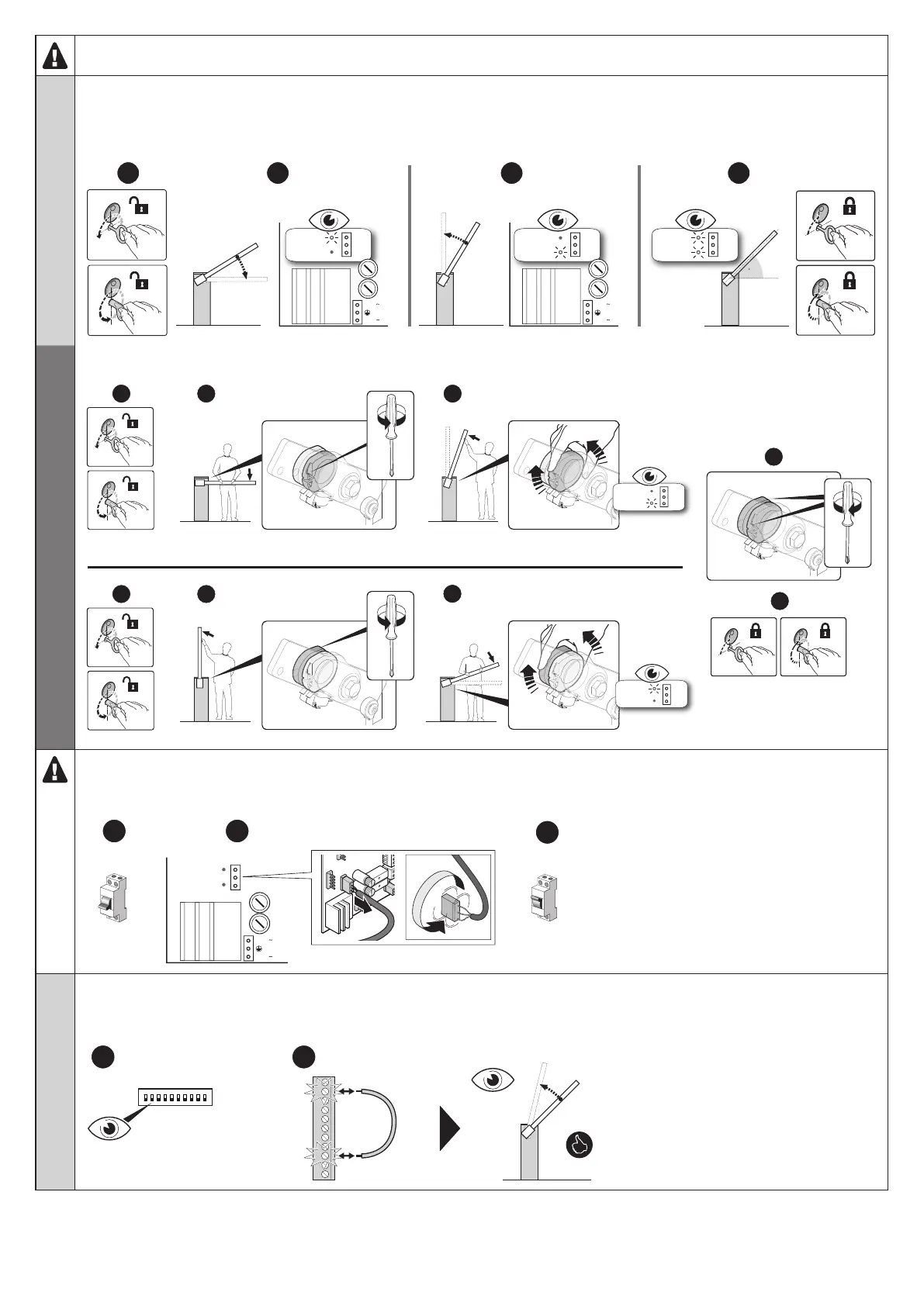
03. check the correspondence between the direction of the manoeuvre and the FCC and FCA limit-switch LEDs
g - manually release the barrier mechanism
h - manually move the boom to the maximum closing position and check that the FCC LED is OFF and the FCA LED is ON
i - manually move the boom to the maximum opening position and check that the FCA LED is OFF and the FCC LED is ON
l - move the boom to 45° and manually lock the barrier mechanism
LED FCC
LED FCA
OFF
ON
g
h
e
ON
o
ON
15
14
13
12
111098765
f
LED OK
1234
5 6 7
8
9
10
LED NA
LED NC
i
24 V
24 V
l
FUSEFUSE
24 V
24 V
45°
LED FCC
LED FCA
ON
OFF
LED FCC
LED FCA
ON
ON
Note - In order to exploit the slowing down function most effectively, it is necessary that the limit switch triggers at about
20° before the mechanical stopping point is reached; if necessary adjust the two cams to set the desired point.
b
a
b
e
d
c
± 20°
± 20°
LED FCC
LED FCA
ON
OFF
LED FCC
LED FCA
OFF
ON
If this does not happen, you need to:
m - cut the mains power supply to the automation
n - rotate through 180° the limit switch connector on the control unit (LIMIT SWITCH - Fig. 5)
o - supply mains power to the automation
LED FCC
LED FCA
OFF
ON
d
g
h
e
ON
o
ON
15
14
13
12
111098765
f
LED OK
1234
5 6 7
8
9
10
LED NA
LED NC
i
LED FCC
24 V
LED FCA
24 V
l
FUSEFUSE
24 V
24 V
nm
24 V
24 V
180°
OFF
LED FCC
LED FCA
04. Verify that the direction of the manoeuvre corresponds to the command sent:
p - set all dip-switches to 'OFF' to have 'hold-to-run' operation
q - with the boom at 45°, give a short command pulse to one of the devices connected to the 'OPEN' input (T1 - Fig. 5) and check that
the movement of the boom is in opening operation
p
15
14
13
12
111098765
q
ON
OFF
1
23
4
5 6 7
8
9
10
 Loading...