VBA10401-R.3623.A
- A23 ・ -
・
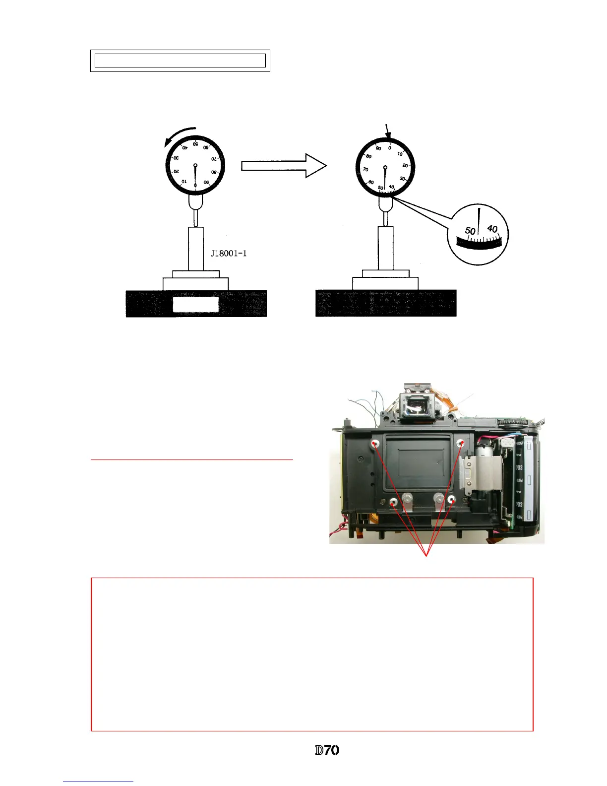
Measure 4 parts from the bayonet face to the CCD-PCB
attaching face.
Standard:48.2±0.015mm/ Parallelism: within 0.015mm
・
In case it is out of standard, make an adjustment
by loosening screws that attach the front and rear
bodies,
or
by putting the washer(s) on the contact
surface between the front body and rear body.
Parts to be measured
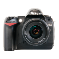
* "0" positioning of the dial gauge
①
Put the tool (J18001-1) on the surface plate, and set the dial gauge to "0".
②
Turn the index ring to shift the position by "0.47 mm" from "0" that was set in
①
.
(This position is "0" of D70.)
③
Measure the body back based on "0" reference position of the index ring.
0" position of D70
Surface plate
Note: For some bodies, washer(s) are already put on the attaching face of the CCD-PCB.
There is an indication of the mark in red at the following 2 positions.
1. Indication: on the camera body side of the CCD-PCB attaching face
Purpose
:
To adjust the height of the camera body
*
By adding the measured value to the thickness of washers, check if it is within the standard
(48.2±0.015mm).
2. Indication: on the CCD-PCB attaching face
Purpose
:
To adjust the height of the CCD-PCB
*
When the CCD PCB is replaced, remove the washers.
Inspection and Adjustment of Body back
 Loading...