VBA10401-R.3623.A
- A41 ・ -
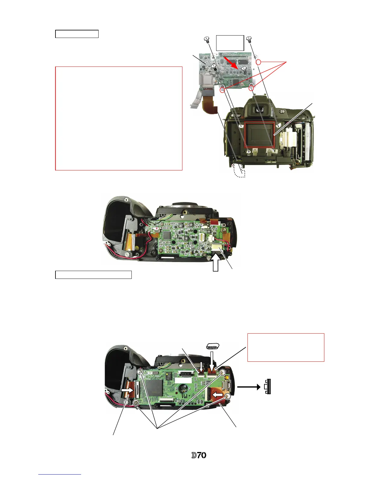
・
Attach the CCD dust-proof seal (#56).
・
Assemble the CCD PCB unit (#B3031) with
4 screws (#669).
CCD PCB unit
・
Attach the CCD PCB connection harness to the connector.
Memory compression PCB
・
Assemble the memory compression PCB (#B2033) and attach it with 4 screws (#679).
・
Attach the USB gasket (#B481) on the memory compression PCB.
・
Put the ferrite core (#1133) on I/F PCB connection FPC.
・
Connect the connection FPCs, which are connected from CF PCB, I/F PCB, main PCB, and CCD PCB to
each connector.
CCD PCB connection harness
I/F PCB connection FPC
CF PCB connection FPC
CCD PCB connection FPC
#B481
#1133
#679×4
#B2033
#669×4
#B3031
#56
*
Note
①:
In case there are washers inserted between the
rear body and the CCD PCB unit, follow the
instructions of Page A23.
*
Note
②:
In case spacers are attached at A parts of the CCD
PCB unit, mount the CCD PCB unit without
removing them.
(
Red mark is indicated on the attachment surface.)
If there are no indications at A parts, spacers are
unnecessary.
A parts
*
Main PCB connection FPC
When adjusting camera body, re-
move this FPC. ref. Page A35.
Direction for
positioning
 Loading...