2 Preparation
22 Nikon N Series/K Series Total Station Instruction Manual
External Device Connector
This connector can be used to connect to an external power source or to communicate
with an external device.
Before using the external device connector, make sure that the external device meets
the specifications below.
C
CAUTION – Except for the connection shown in Figure 7.1 on page 152, use of this connector
is at your own risk.
C
CAUTION – Use only the male connectors specified above. Using other connectors will
damage the instrument.
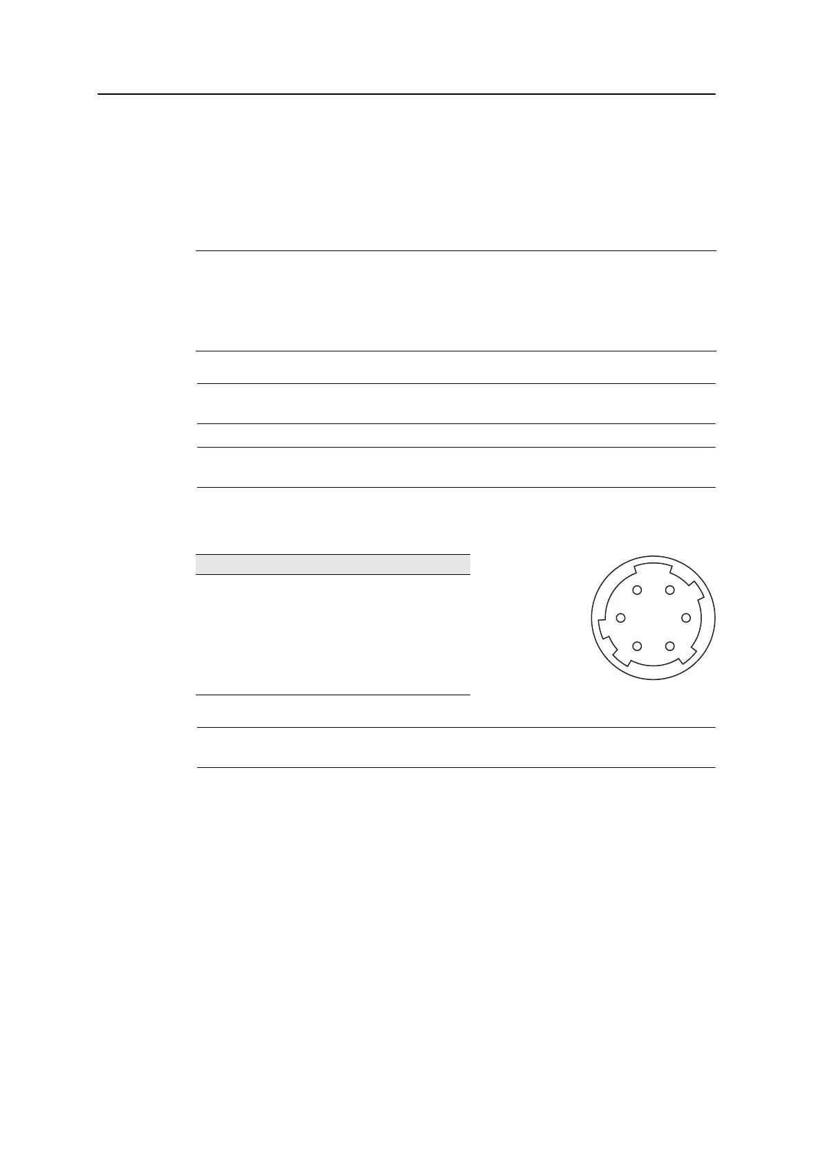
The external device connector is a Hirose HR 10A-7R-6S female connector. The
pinouts for connecting it to an external device connector are shown below:
C
CAUTION – Use only the pin connections shown above. Using other connections will damage
the instrument.
To communicate with an external device, connect the RS-232C signal from the
external device to Pin 1 (input terminal) and to Pin 2 (output terminal) on the
instrument.
Cap the data output/input connector securely while not in use. The instrument is not
watertight if the cap is not attached or not attached securely, and when the data
output/input connector is in use.
The instrument can be damaged by static electricity from the human body discharged
through the data output/input connector. Before handling the instrument, touch any
other conductive material once to remove static electricity.
Input voltage 4.5 V to 5.2 V DC
System RS-232C
Signal level ±9 V standard
Maximum baud rate 38400 bps asynchronous
Compatible male connector Hirose HR10A-7P-6P or HR10-7P-6P
Pin Signal Description
1 RXD Receive data (Input)
2 TXD Send data (Output)
3 NC No connection
4VPower
5 GND Ground
6 NC No connection
 Loading...