Wall installationWall installation
Preparing installationPreparing installation
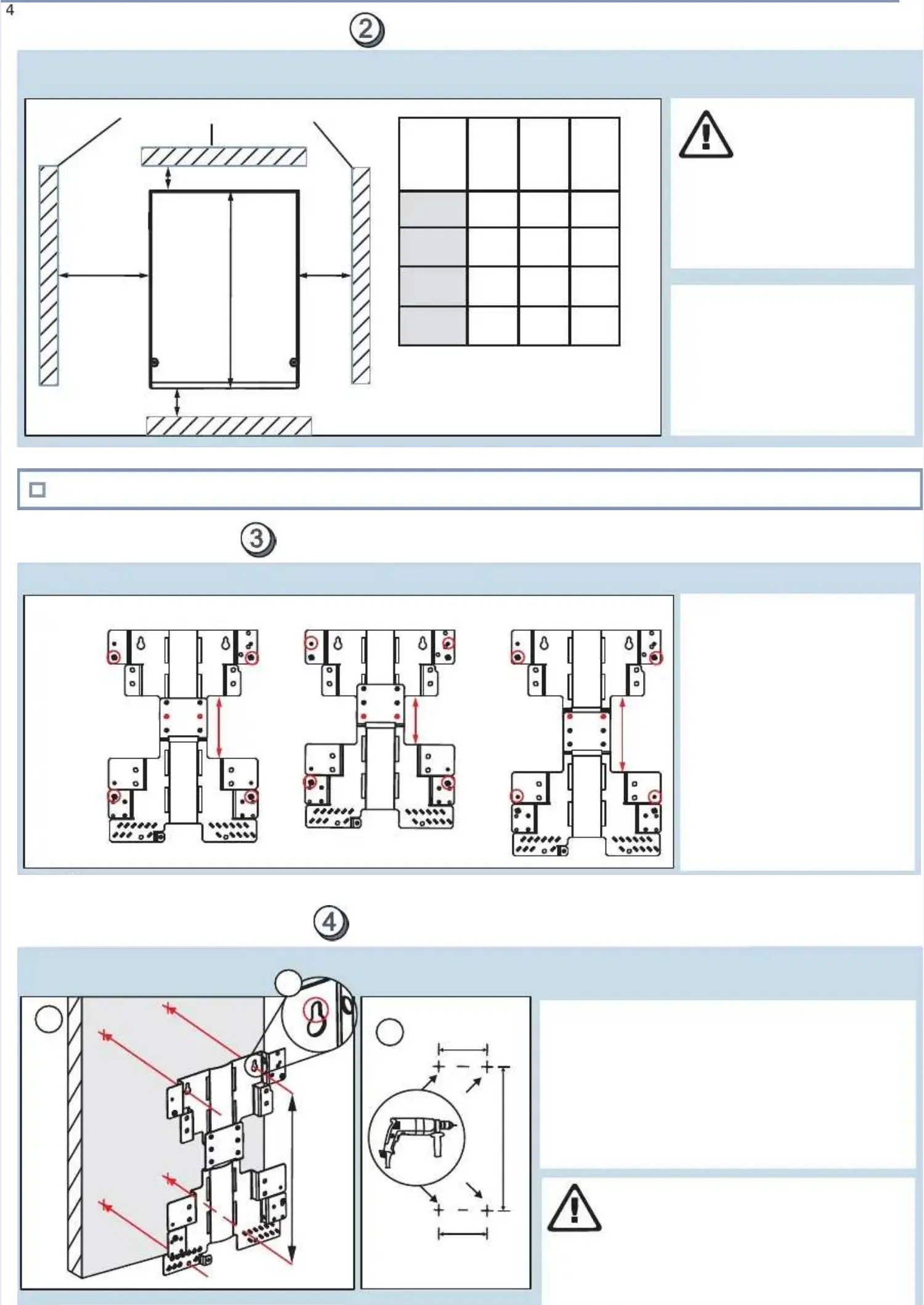
ClearancesClearances
Fixing studsFixing studs
aa) ) bb) ) cc))
Fixing studsFixing studs
Mounting bracket assemblyMounting bracket assembly
Fix the two bracket partsFix the two bracket parts
together and screw in thetogether and screw in the
four fixing studs. There arefour fixing studs. There are
three ways to connect thethree ways to connect the
bracket parts:bracket parts:
a)a)
b)b)
c)c)
Middle position - used in theMiddle position - used in the
documentdocument
Short positionShort position
- recommended for pole- recommended for pole
installationsinstallations
Long positionLong position
- - --
Check listCheck list
Site meets the minimum clearances.Site meets the minimum clearances.
Marking and drilling holesMarking and drilling holes
185 mm185 mm
(7.3 in.)(7.3 in.)
*)*)
11
*)*)
11. . MMaarrk k oon n tthhe e wwaallll
using the bracket as a templateusing the bracket as a template
rill the holes.rill the holes.
*) The distance between upper and lower holes*) The distance between upper and lower holes
dedepependnds s on on chchososen en brbracackekett
connection length.connection length.
the locations of mounting holesthe locations of mounting holes
..
..
2. Note that the upper part of the hole defines the2. Note that the upper part of the hole defines the
maximum fixing screw size.maximum fixing screw size.
3. 3. DD
thethe
Mark the upperMark the upper
holes firstholes first
TT
aa
tt
he fixing method must be sufficient tohe fixing method must be sufficient to
keep the unit at its position. Always choosekeep the unit at its position. Always choose
method and fixing screws that aremethod and fixing screws that are
adequadequate ate o the suro the surfaceface
construction type/material.construction type/material.
CCAAUUTTIIOONN! ! ppeerrssoonnaal l iinnjjuurryyRRiissk k oof f ..
185 mm185 mm
(7.3 in.)(7.3 in.)
C C aannd d ffiixxiinng g ppooiinnttsslearanceslearances
TTopop
LeftLeft
Walls / roofs / floors / other objectsWalls / roofs / floors / other objects
RightRight
CAUTION!CAUTION!
personalpersonal
injuryinjury
Risk ofRisk of
..
EEnnssuurre e tthhaat t iinnssttaallllaattiioonn
surface and selected fastenerssurface and selected fasteners
ccaan n ddeevviicce e uunnddeer r
required circumstancesrequired circumstances
the wallthe wall
sustain thesustain the
tthhe e ..
L = 431 mmL = 431 mm
(16.97 in.)(16.97 in.)
22
33
NOTICE:NOTICE: The unit cooling airflowThe unit cooling airflow
goes from the goes from the left-left-hand side tohand side to
the right-hathe right-hand side nd side of the of the unit.unit.
unit isunit is
installed in a room that enablesinstalled in a room that enables
proper ventilation.proper ventilation.
Make sure that theMake sure that the
BottomBottom
* 200 mm needed for fans' maintenance* 200 mm needed for fans' maintenance
when module is in its installation positionwhen module is in its installation position
** 60 mm (2.36 in) is the minimum when** 60 mm (2.36 in) is the minimum when
installing in a small space (special case)installing in a small space (special case)
MiddleMiddle
andand
longlong
positionposition
ShortShort
positionposition
CabinetCabinet
installa-installa-
tiontion
Left*Left*
50 mm50 mm
(1.97 in.)(1.97 in.)
50 mm50 mm
(1.97 in.)(1.97 in.)
50 mm50 mm
(1.97 in.)(1.97 in.)
RightRight
50 mm50 mm
(1.97 in.)(1.97 in.)
50 mm50 mm
(1.97 in.)(1.97 in.)
TTopop
50 mm50 mm
(1.97 in.)(1.97 in.)
20 mm20 mm
(0.78 in.)(0.78 in.)
Bottom**Bottom**
200 mm200 mm
(7.87 in.)(7.87 in.)
200 mm200 mm
(7.87 in.)(7.87 in.)
200 mm200 mm
(7.87 in.)(7.87 in.)
MountingMounting
bracketbracket
assemblyassembly
positioningpositioning
50 mm50 mm
(1.97 in.)(1.97 in.)
50 mm50 mm
(1.97 in.)(1.97 in.)
 Loading...