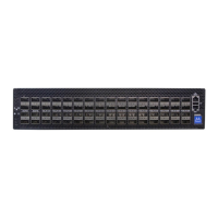
• •Power (rear) side inlet to connector side outlet
- marked with blue dots that are placed on the
power inlet side.
Connector (front) side inlet to power side
outlet - marked with red dots that are placed
on the power inlet side.
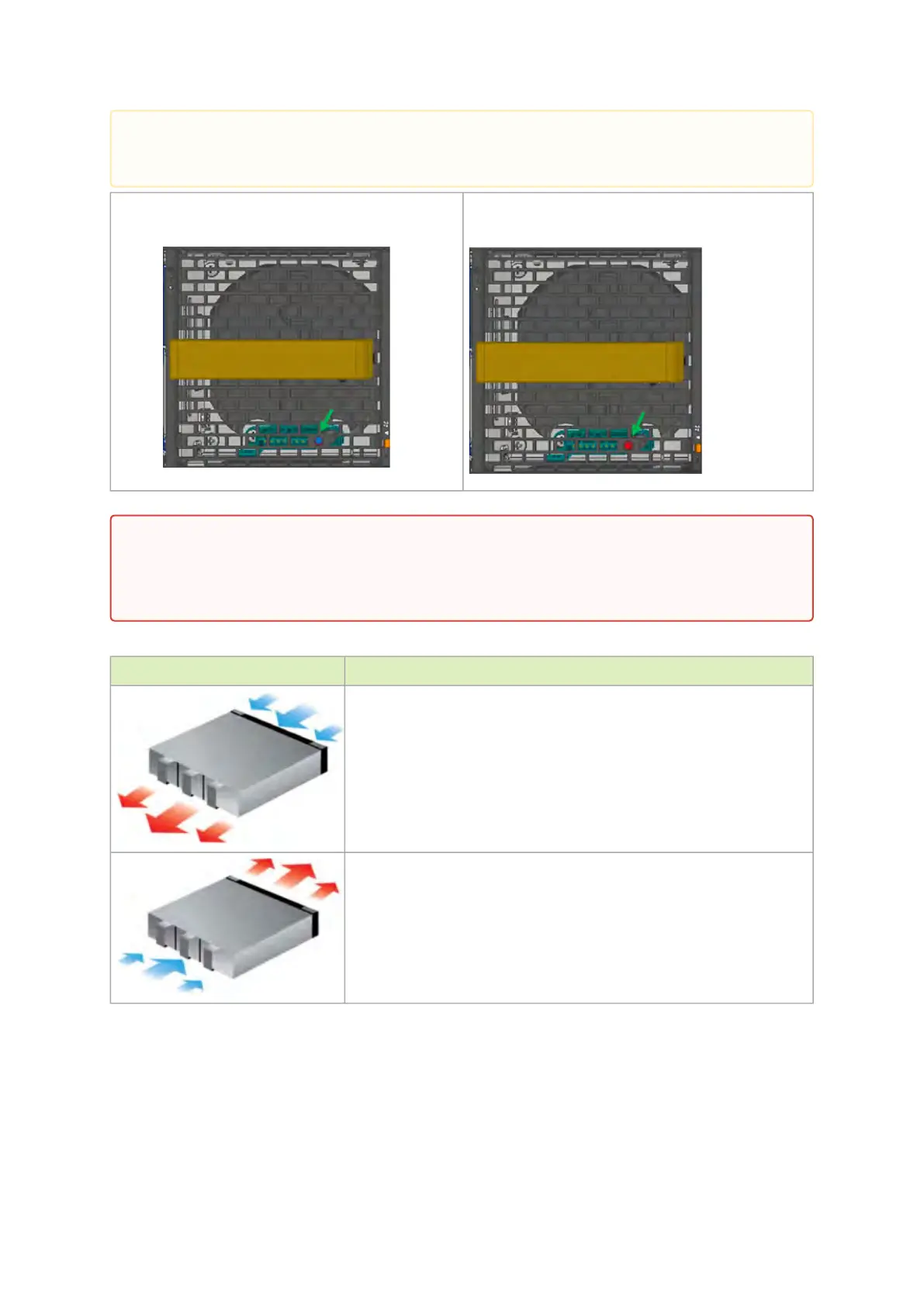
The table below provides an air flow color legend and respective OPN designation.
Direction Description and OPN Designation
Connector side inlet to power side outlet. Red dots are placed on the
power inlet side.
Power side inlet to connector side outlet. Blue dots are placed on the
power inlet side.
Package Contents
Before installing your new system, unpack it and check against the parts list below that all the parts
have been sent. Check the parts for visible damage that may have occurred during shipping.
the images are provided for illustration purposes only. The design may slightly vary in
different systems
All servers and systems in the same rack should be planned with the same airflow direction.
All FRU components need to have the same air flow direction. A mismatch in the air flow
will affect the heat dissipation.
 Loading...