14
Fig. 18
Clockwise Counterclockwise
Right hand knobs 230° 20°
Left hand knobs 20° 230°
Fig. 19
Fig. 20
@
@
²
³
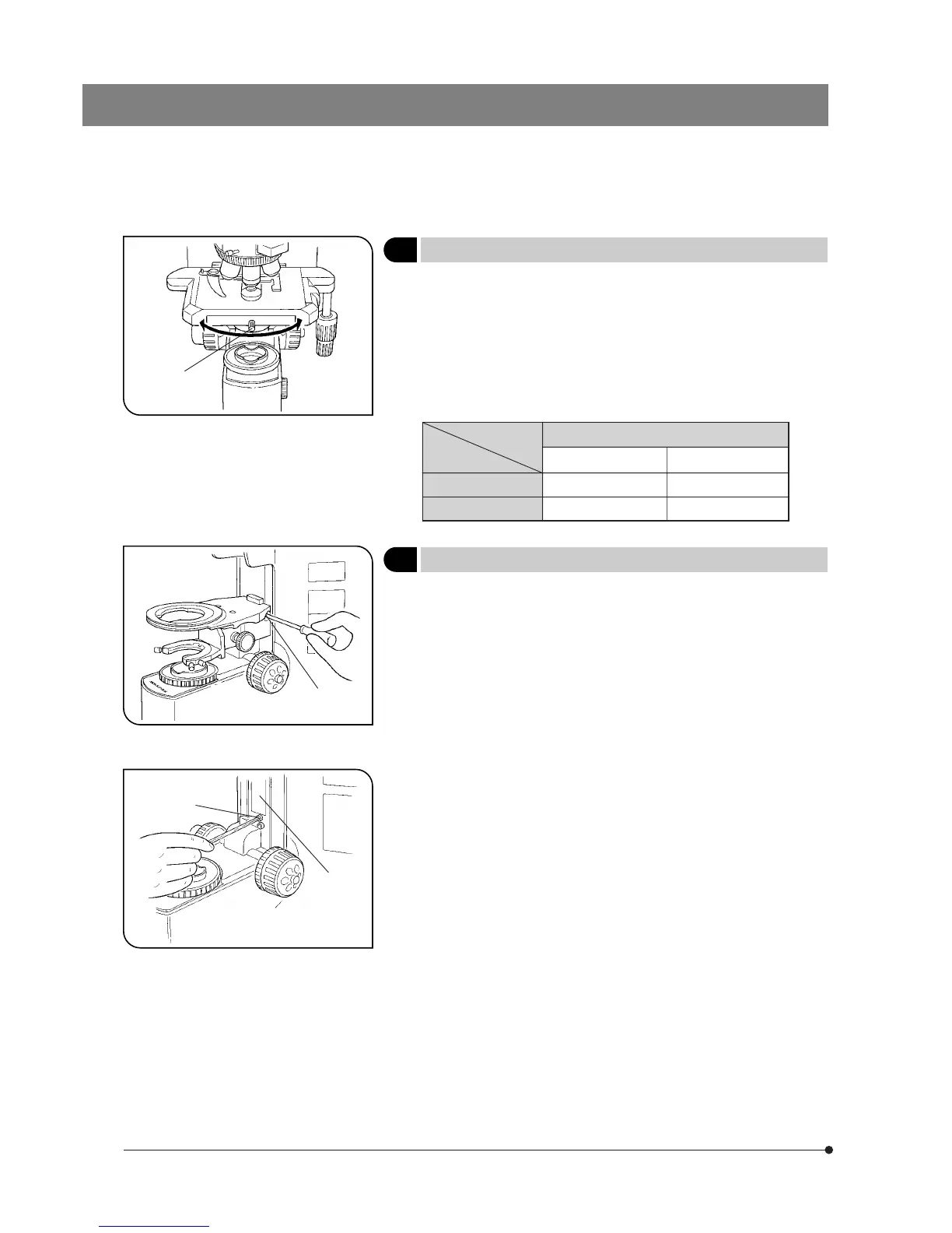
3 Rotating the Stage
(Fig. 18)
1. Slightly loosen the stage clamping screw @.
2. The stage can be rotated both clockwise and counterclockwise by the
stage clamping screw.
#A click may be heard and felt during rotation. However, this is due to
the construction of the substage and does not indicate a malfunc-
tion.
}The angle of rotation varies depending on the positions of the X- and Y-
axis knobs.
4 Adjusting the Stage Height
(Figs. 19 & 20)
}By lowering the position of the substage, the microscope will accommo-
date specimens with maximum height of 35 mm. This is useful when
observing metallurgical specimens and other thick objects.
1 Lower the stage to the lower limit, then remove the stage from the micro-
scope.
2 Using the Allen screwdriver, loosen the substage bracket clamping screw
@ and remove the substage.
3. Turn the coarse adjustment knob and raise the focusing block ³ to
where the stopper screw ² on the arm becomes visible.
4. Using the Allen screwdriver, loosen and remove the upper stopper screw
².
5. Reattach substage bracket and stage.
Angle of Rotation
 Loading...