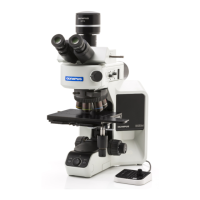
28
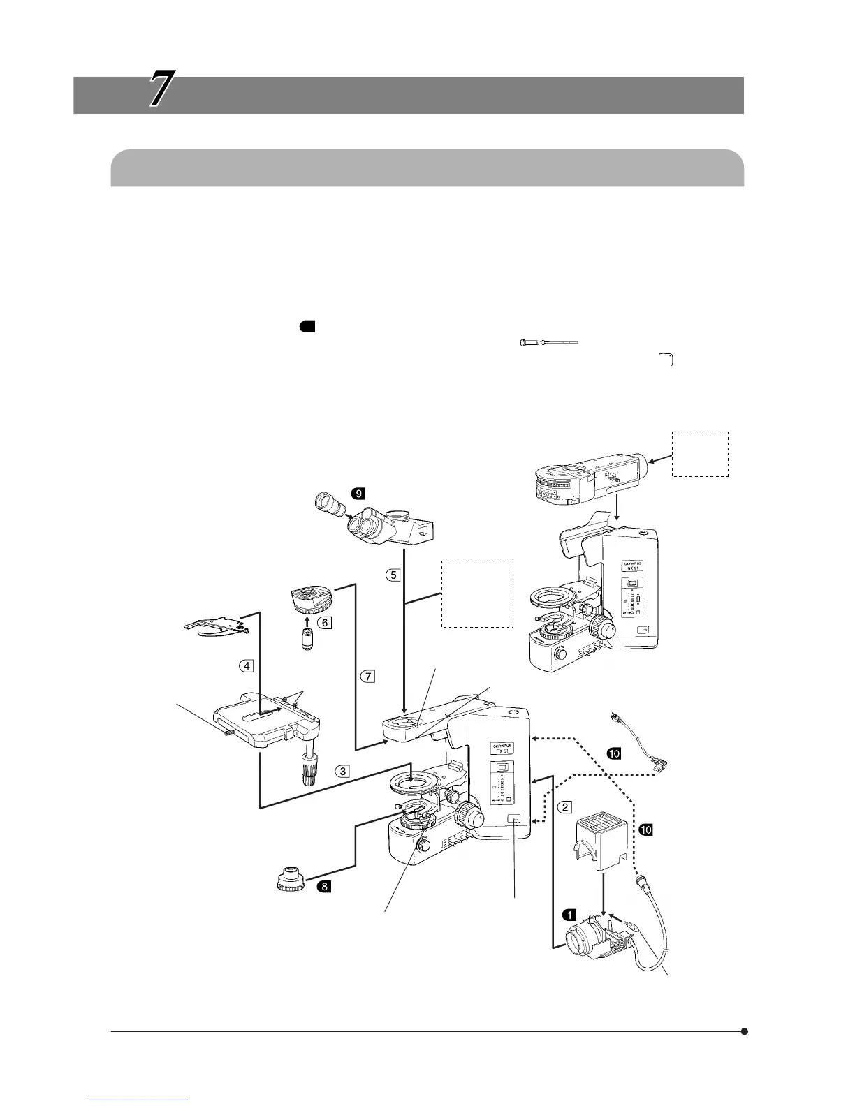
The diagram below shows the sequence of assembly of the various modules. The numbers indicate the order of
assembly.
The BX51TRF microscope frame is assembled in the same procedures as the BX51TF frame.
The module numbers shown in the following diagram are merely the typical examples. For the modules with which the
module numbers are not given, please consult your Olympus representative or the catalogues.
# When assembling the microscope, make sure that all parts are free of dust and dirt, and avoid scratching any
parts or touching glass surfaces.
Assembly steps enclosed in will be detailed on the subsequent pages.
}Most assembly operations are possible by using the Allen screwdriver ( ) provided with the microscope.
However, the assembly of the reflected light illuminator requires the use of the provided Allen wrench (
) for clamping
the internal screws (to ensure the performance, we recommend that you have your Olympus representative assemble or
remove this module).
ASSEMBLY
7-1 Assembly Diagram
Eyepiece
WHN10X (FN 22)
WHN10X-H (FN 22)
35WHN10X (FN 22)
SWH10X-H (FN 26.5)
35SWH10X (FN 26.5)
Observation tube
U-BI30-2 (FN 22)
U-TR30-2 (FN 22)
U-TR30NIR (FN 22)
U-TBI3 (FN 22)
U-SWTR-3 (FN 26.5)
U-ETBI (FN 22)
U-TTBI (FN 22)
Intermediate
attachment
U-EPA2
U-DO3
U-TRU, etc.
Tube clamping
screw
Revolving nosepiece
U-5RE-2
U-D6RE
U-D7RE
U-P6RE
Specimen holder
clamping knobs
Specimen holder
U-HLDT-4
U-HRDT-4
U-HLST-4
UIS2/UIS
series
objective
Stage
U-SVRB-4
U-SVLB-4
U-SRG
Stage clamping
knob
Condenser
U-AC2
U-SC3
U-AAC
U-ULC-2
U-UCD8
Reflected light illuminator
BX-URA2
BX-RFA
BX-RLA2
Microscope frame
BX51TRF
Power cord
100 W halogen bulb
12V100WHAL-L
12V50WHAL-L
100 W halogen
lamp housing
U-LH100-3
Lamp socket
clamping screw
Microscope frame
BX51TF
Condenser clamping
knob
Reflected
lamp
housing
Revolving nosepiece
clamping screw
 Loading...