10 11
NOMENCLATURE
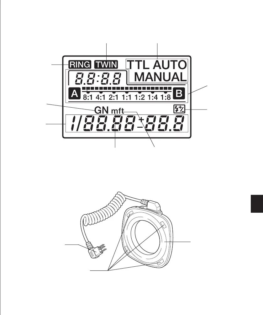
Control Panel Display
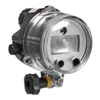
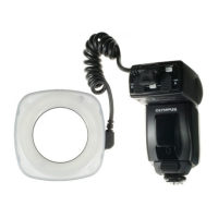
Macro Flash Controller FC-1
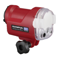
Ring Flash RF-11
Connector terminal
(Page 15)
Ring Flash connector
(Page 15)
Ring Flash release
button (Page 15)
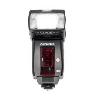
Twin Flash release
button (Page 28)
Twin Flash connector
(B) (Page 27)
External power connector
Connect the optional HV-1
Flash High-Voltage Pack.
Te rminal cover
Lock pin
(Page 14)
Electrical con-
tact (Page 14)
Lock ring
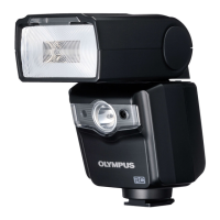
Control panel
Panel light button
Press to light up the control
panel for about 15 seconds.
The control panel lights up
when controlled by a digital
camera with communication
capability.
Dial A
Dial B
Mode button (Pages 18 & 31)
Lamp button (Pages 19 & 33)
Auto Check lamp
(Pages 20 & 34)
Battery compartment cover
(Page 13)
Charge lamp/Test button
(Pages 16 & 29)
Power button
* For simplicity, this figure shows the panel with all indicators lit.
Ring Flash
Twin Flash Control mode
Twin Flash light
ratio display
(Pages 36& 40)
Light intensity
adjustment
(Pages 21, 23,
35 & 39)
Guide number
(GN)
Meter (Page 46)
Feet (Page 46)
Setting display
(GN, light intensity
and light intensity
adjustment)
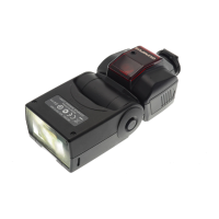
Light emitting window
Illuminator
(Page 19)
Twin Flash connector
(A) (Page 27)
 Loading...